|
|
 09-21-2016, 03:02 PM
|
#11
|
|
Senior Member
Join Date: Aug 2016
Location: Reno, NV
Posts: 1,420
|
Bumping this thread in case anyone knows.
My van has no upfitter switches. I went looking for the wiring harness in the dashboard, have not located it yet.
I did find the blunt ends up high in the engine compartment with a bunch of other blunt ends. The colors matched as did the wire gauge (1 and 2 are 30Amp, 3 15 amp, 4 10amp).
According to that 2012 wiring diagram, the relays are in the battery junction box as are the fuses. The relay spots were empty. Did not check the fuse spots but I suspect the same.
This leads me to believe that there is no separate relay box, you simply have to add the correct fuses and relays to the batter junction box.
Now to find that Upfitter switch wiring harness................
My trailer brake controller harness is there. Gotta be there some place.
|

|

|
|
09-21-2016, 04:51 PM
|
#12
|
|
Senior Member
Join Date: Sep 2013
Location: Newberg, OR
Posts: 1,385
|
I've got a few spare wiring harnesses and all of the Battery Junction Boxes have the upfitter circuits populated. Some of those wires go up to the spot under the hood with the loose ends like you mentioned, the other side of those circuits go through the firewall pass through and into connector 219 which connects to the main dash harness (large connector, lever action type, located under steering column).
The aux switch wires then branch off above the dog house opening towards the left side.

Connector 2388 is grey, 8 position, Molex HDAC series,
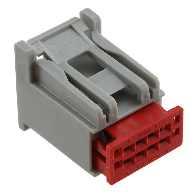
Wire colors are:
Green/Blue
Violet/Grey
Black/Grey
Grey/Brown
White/Violet
White/Blue
Green
If your dash wiring harness doesn't have these wires, they can be added in easily. Just get some crimp terminals for connector 219 and one of the 8 position connectors from Mouser.com.
|
|
|
|
|
09-21-2016, 05:10 PM
|
#13
|
|
Senior Member
Join Date: Aug 2016
Location: Reno, NV
Posts: 1,420
|
mg you are awesome!
I found that trailer brake controller in that area, but had to get back to work so I couldn't dig any deeper.
Each and everything you said checks out on the wiring diagram and I see C219 listed. Thanks a bunch. I am betting it's in there some place and good to know the wiring is present in the battery junction box.
My plan is to tie in lighting to all of these, particularly some perimeter porch type lighting all around the van. Trying to dot my i's and cross my t's.
|
|
|
|
|
09-21-2016, 05:21 PM
|
#14
|
|
Senior Member
Join Date: Sep 2013
Location: Newberg, OR
Posts: 1,385
|
Quote:
Originally Posted by Flux

...Each and everything you said checks out on the wiring diagram...
|
 that might be because I've almost memorized the van's wiring diagram in the process of integrating the Cummins wiring.
|
|
|
|
|
09-21-2016, 05:33 PM
|
#15
|
|
Senior Member
Join Date: Aug 2016
Location: Reno, NV
Posts: 1,420
|
Quote:
Originally Posted by mgmetalworks
that might be because I've almost memorized the van's wiring diagram in the process of integrating the Cummins wiring. |
That is one heck of a project. That van will be a monster!
|
|
|
|
|
09-23-2016, 09:47 AM
|
#16
|
|
Senior Member
Join Date: Aug 2016
Location: Reno, NV
Posts: 1,420
|
Had a few moments last night to sort through the wiring harness.
Good news is I found the relay trigger wires in that big lever action harness. Bad news is they are only on one side of the harness centered below the steering wheel. The Upfitter switch plug should Y off with the trailer controller plug (I have that one), but it doesn't. Now I gotta hunt down the green 10A DC+ line (Green) that would feed from the IP or Smart junction box. I'm a little concerned this one doesn't exist, reason being that if they didn't put the Upfitter switch plug in there, then maybe their procedure is to not leave any hot wiring around that isn't used. kind of hope I'm wrong here though. It might be in the other lever action harness down there. It's a nice mess for sure.
Thanks for pointing me in the right direction MG, much appreciated. This is still the easiest and cleanest way to put some dash switched lighting in.
|
|
|
|
|
09-23-2016, 10:41 AM
|
#17
|
|
Senior Member
Join Date: Sep 2013
Location: Newberg, OR
Posts: 1,385
|
In my experience so far, it appears as though there are only a few configurations of the BJB harness (main harness under the hood) so the up fitter relay wiring is likely to be in the majority of them. Every one I've seen to date has had the wiring, even on vans without the aux switches.
The under dash harness has way more configurations. I bet there are many many part numbers, some with and some without the aux switch wiring.
I pulled out a loose BJB harness and you can see the up fitter relays populated...

On the bottom side, you can trace the switch trigger wires from the relay...

to the connector under the dash...

Most of the wiring is there. I don't have the other side of the connector handy otherwise I'd take some pictures of the terminals. If they're a molex or tyco terminals, you can find them easily. Yazaki is the difficult brand to source. I'll see if I can round up the part numbers. I have to take my dash harness out soon anyway. I might need some.
|
|
|
|
|
09-23-2016, 10:51 AM
|
#18
|
|
Senior Member
Join Date: Sep 2013
Location: Newberg, OR
Posts: 1,385
|
The Smart Junction Box has many configurations but most of the fused circuits are populated even if the wiring in the dash harness isn't there. What I've done for adding circuits (for my power mirror functions) is to find a fuse that isn't used, find the connector it resides in at the SJB connection and then add in a wire to that connector using the appropriate crimp terminal. In my van's config, there are something like 16 fused circuits that are unused. Some of those are part of the "smart" functions and I leave those alone but there are still many ign hot or 12v+ continuous fused circuits one could make use of by just plugging a wire into a connector.
|
|
|
|
|
09-23-2016, 01:04 PM
|
#19
|
|
Senior Member
Join Date: Aug 2016
Location: Reno, NV
Posts: 1,420
|
Those look like the white blue and white violet leads for the 30 Amp upfitter circuits. According to the diagram they were next to each other as were the grey brown and grey orange which are on the other side of the harness. Those I found with your help. The wiring diagram is key and actually tells you the fuse positions as well as the relay positions to get all this going too. There's also a bunch of "customer access wires" in there too, I might hunt a few down just so I have some more auxiliary power leads for various stuff like rear view cameras etc.
I will document what I find out and post it so that others can follow along. The hardest part is sorting through these bundles.
My thought right now is to clip those leads and put them on another quick disconnect to save the hassle of digging up every crimp end under the sun. I ordered the molex 30700 series female end and crimps though to plug into the upfitter switch panel properly as there is no way around that one.
I can also live without the illumination circuit. Might be bothersome anyway as it's just below eye level when driving. But if it's around, I will give it a go.
Not really sure why they call it a smart junction box. Hopefully it doesn't have to be flashed or anything to initiate the 10Amp trigger circuit, although I could certainly bypass that somehow.
Shame my version of the harness is missing the Upfitter wiring and it seems silly as the trailer control wiring is there.
Thanks very much for the help on this. It seems trivial, but it's a very useful setup
|
|
|
|
|
09-23-2016, 02:46 PM
|
#20
|
|
Senior Member
Join Date: Sep 2013
Location: Newberg, OR
Posts: 1,385
|
Quote:
Originally Posted by Flux
...Not really sure why they call it a smart junction box...
|
The SJB is essentially a circuit board with some microprocessors and CAN components plus all of the fused circuits. some of the circuits have programmable features and some circuits are linked to the CAN buses so that's where the "smart" comes in.
|
|
|
|
|
|
 Posting Rules
|
You may not post new threads
You may not post replies
You may not post attachments
You may not edit your posts
HTML code is Off
|
|
|
|
 » Recent Threads
 |
|
|
|
|
|
|
|
|
|
|
|
|
|
|
|
|
|
|
|
|
|
|
|
|
|
|
|
|
|
|
|
|
|


 Linear Mode