|
|
 03-15-2015, 08:44 PM
|
#11
|
|
Senior Member
Join Date: Feb 2012
Posts: 879
|
Re: Does alternator know how many amps to send to the Batter
This is a bit rambling, but...
I just helped a friend re-do much of the electrical (house DC system) plus add solar to my former '97 SMB. The one thing he didn't want to do was the "alternator wire" (i.e. the wire that brings charging back from the Ford alternator/Surepower separator to the house bank). I *really* wanted to replace it as it was a skinny little wire (#8 I believe), with a really weeny/cheap looking fuse up by the separator, and no fuse on the house bank end. It's actually pretty close to even be able to fuse #8 for the actual load being put on it (a good sign that larger wire would be better!). I think he was just sick of the project and wanted to be done with it, but I sure wanted to put a #2 wire in there!
On top of that on this SMB the wire simple "came out of the wall" near the fuel filler area (where much of the 12-volt and 110 wiring comes out), so there was really no way to see if it was chafe-protected, etc. where it ran inside the wall.
I just helped another friend upgrade an E-450/V-10 based RV, and his had #6 wire from the builder. We changed it to #2, which we could adequately fuse both for charging (he typically sees 60 amps getting back to the house batts, at first), and for combining the banks to "self jump start" (200 amp fuse). There is still some voltage drop, but it's a lot better than it was.
I don't know about the 460, but I read (I think it was in a search here, from Scalf77) that the V-10 draws around 150 amps when starting (the inrush current is more, but that doesn't "count").
With a larger house bank there is a lot of capacity for putting out amps if a wire chafes through or etc. For example, in my buddy's SMB we just did, we put in two Lifeline Group 31 XL AGMs (125 ah each). I don't remember the exact short circuit current rating for the pair, but I think it was between 8,000 and 9,000 amps. Hence the need for a fuse with an AIC rating (Ampere Interrupt Capacity) that would handle that. We used Blue Sea MRBF holders and fuses - they rated for 10,000 AIC. This is separate from the amp rating of the fuse (which would be, say, 200 amps or whatever is appropriate for the wire size used). The possible issue with an underrated fuse is that even if you have the correct size fuse in there, the fuse holder just welds shut or is otherwise rendered dysfunctional if there is a short. This seems to be a newer concern as people start to routinely put in larger battery banks. (Not that two Group 31s is all that large even!).
Although he didn't replace the "alternator wire," we did wire up a new DC house distribution system, and the wire coming off the house bank to the positive bus got a 10,000 AIC rated main fuse (200 amp fuse). (I would like to have done the alternator wire too - perhaps he will do that in future.)
|

|

|
|
03-15-2015, 09:19 PM
|
#12
|
|
Senior Member
Join Date: Jan 2013
Location: Lake Tahoe
Posts: 216
|
Re: Does alternator know how many amps to send to the Batter
Nice ramble. Never heard of AIC rating. Time to bone up.
My self jump start is just that, self. I carry 16 foot jumper cables that just barely reach. I tried it once and it worked.
I wanted #2 wire right of the bat. Then I saw the price  Hey, my first smily I don't even know if that is the right one. My best option so far is #2 jumper cables from Auto Zone and make my own ends, but still.
I bet the '97 is just like my '96 so it is #8 I have. I have no fuse at the battery either.
This is the last task of my beer budget electrical system. I had another thread about big block generator or 460 generator. I am wasting gas but saving so much on capital cost.
Essentially I have $65 worth of 1500 inverter hooked up to the starter battery. Plug the shore power cord to the inverter, start the van, run the microwave for 4 min. and the coffee maker for 13. Then just let it run until a half hour has past and there seems to be enough in the house battery until the next morning. The house battery is on its last legs.
So I want to buy two walmart group 27 marine batteries http://www.walmart.com/ip/EverStart-...ttery/16795212 that are listed in some places as true deep cycle. I know two 6 volt in series is better than 2 12volt in parallel etc. but they are like $82 a piece so I can't go too wrong. I will buy them at the same time in some hope they match well. For a battery box I just need to hit a Contigo 26" http://www.homedepot.com/p/Contico-2...BK-1/202559503 with a hole saw to vent the bottom and the side for the vent hose I have already. I think I will have to shave the handles of the batteries to fit in the box too. The tool box is like $35. Then maybe I won't have to run the engine longer than the coffee maker.
But that 20 feet of #8 wire with no fuse at the battery is more scary than my redneck electrical math. Hence the post and thanks to all. It has helped. Now to ask Jeeves about AIC ratings.
__________________
1996 Ford EB 2 wheel drive 460
|
|
|
|
|
03-16-2015, 05:29 AM
|
#13
|
|
Senior Member
Join Date: Jan 2011
Location: Reynoldsburg, Ohio
Posts: 3,774
|
Re: Does alternator know how many amps to send to the Batter
Quote:
|
Originally Posted by xcnick
However this begs a good question. How do I add amp gauges into the van?
|
Interior mounted read outs for any amperage requires the gauge or read out device be inline with a shunt. Running in excess of 100 amps DC continuously inside the cabin is fraught with all sorts of dangers, over heating being one of the biggest.
I would also love an alternator output gauge but given the issues that introduces and going with many alternator manufacturers a charging voltage meter is a very close second best way to monitor the alternator health.
|
|
|
|
|
03-16-2015, 10:54 AM
|
#14
|
|
Senior Member
Join Date: May 2007
Location: Beaverton, OR
Posts: 2,505
|
Re: Does alternator know how many amps to send to the Batter
With a isolator you have current travelling only in one direction, so the wire and fusing needs to be their to protect that. Your extra current capacity would flow down that path to "charge " the battery while running. You can't start the engine with the house battery using the isoaltor circuit, so you really don't need to worry about inrush etc. I would have a 50 amp fuse/ breaker on the output of the isolator and back at the battery. You could make it a main circuit, but I think it would be better as a branch behind your main battery fuse.
When you add a second battery you will increase capacity of the battery bank, but staying with in safe levels of discharge should not effect the output of the alternator anymore then your previous one battery setup other then the duration to charge.
Quote:
|
Originally Posted by xcnick
Nice ramble. Never heard of AIC rating. Time to bone up.
Essentially I have $65 worth of 1500 inverter hooked up to the starter battery. Plug the shore power cord to the inverter, start the van, run the microwave for 4 min. and the coffee maker for 13. Then just let it run until a half hour has past and there seems to be enough in the house battery until the next morning. The house battery is on its last legs.
|
So in that configuration with a isolator you running your microwave/coffee maker off of your starting battery. I expect at idle you are not even putting out enough amps to keep up with the load, so you are depleting your starter. If you have a charger on your house side then you may also be charging your house battery for the last half hour. It would be a guess how much is getting back into the starting battery, but I expect you are prematurely killing it. You need to tie the inverter to the house battery and then run the coffee pot and microwave directly off of that.
What are you goals, and maybe we can help you get there.
-greg
__________________
-greg
__________________________________________________ ______________
"Goldilocks" 2020 Ford Transit High Roof Extended 3.5 EcoBoost AWD Homebuilt
|

|
|
|
03-16-2015, 11:30 AM
|
#15
|
|
Senior Member
Join Date: Jan 2013
Location: Lake Tahoe
Posts: 216
|
Re: Does alternator know how many amps to send to the Batter
Quote:
|
Originally Posted by Scalf77
I expect at idle you are not even putting out enough amps to keep up with the load, so you are depleting your starter. ...but I expect you are prematurely killing it.
|
That was my worry too so I tried it 3 days in row at home in case the starter battery failed. When the alternator gets demand from the inverter the idle automatically goes up on the van which helps. Then after the routine I checked the starter battery with one of those battery checkers which apply a load for so many seconds. I was amazed the starter battery was the same after this little routine as before the routine.
Now I have done two trips with this similar routine and so far so good. Both my batteries are older so I will never now if this killed the battery prematurely or if it died of old age, but so far so good.
Measuring amps of course would be better than trial and error, but I really think with the advanced idle the alternator is close to keeping up and the extra 15 min. makes up the difference.
The extra 15 min. does not top off the house battery however. It just gives me a little boost to make it a little longer.
My goal now is to get more out the house battery. I don't always use the microwave in the morning or drink coffee. I hope to be able to keep the 12 volt fridge running more days without having to tank up the house battery. Maybe start the van once every 3 days rather than everyday.
thanks
__________________
1996 Ford EB 2 wheel drive 460
|
|
|
|
|
03-16-2015, 12:55 PM
|
#16
|
|
Senior Member
Join Date: Feb 2012
Posts: 879
|
Re: Does alternator know how many amps to send to the Batter
True that with the Surepower isolator you can't "self jump start" with that cable - I probably muddied things with that comment. I'm taking out the isolator and going with a manual switch, so I'm planning for self jump start capability (the larger wire will also give me less voltage drop from the alternator, not that it's still a very good charger). My other option was a Blue Sea 7622, but I decided to do the manual switch (and could always change to the Blue Sea). I have the switch behind the seat where I can reach it from cab or rear, and that is also where I would put the 7622 (they all say to mount in dry location - I don't count the fenderwell in that spec...)
If you would like a really thorough "cookbook" approach to great wiring practice, ABYC standards for boats are top notch, and deal with many of the same situations (although they do not have chassis grounds). My background is in boating, so I already knew of it.
The basic idea is that you size the wire for the load(s), and then size the fuses or breakers for the wire. If you can't safely fuse a given wire for its expected load, then that tells you to go up a wire size. In practice, I find that most of my larger DC wire runs are oversized for avoiding voltage drop anyway. One way to find out the ampacity of the wire (which guides your fuse sizes) is to Google "ABYC Ampacity table." Note that wires have to be de-rated if they are bundled or run through an engine compartment (heat). Blue Sea also has some nice tools (including ABYC info) on their site.
So, you start out with a fuse on the battery that is sized for the jumper wires and the initial wire leading to a positive bus (say you use 2/0 and have a 200 amp fuse, just for an example). Then maybe you have a #2 wire leading to your solar controller. Usually when a wire goes down in size you need a new fuse. So maybe you put a 130 amp fuse on that wire (right where it branches off the positive bus, so all wire is protected). Then maybe the wire to your 110 charger is #6, so that would take an 80 amp fuse or similar. A main feed wire to the 12-volt panel might also be #6, so it could come off the same fuse, or a separate one for easier troubleshooting (a breaker rated as a switch and/or a switch is nice here to "turn off" power to the panel for various reasons). Then all the "little" wires from your 12-volt fuse block get their own fuses according to their size/ampacity rating (typically 10-20 amp fuses on 14/12 wire size).
On the '97 SMB I couldn't quite figure out their fusing scheme. For example, they had drilled into the 12-volt fuse block (house power distribution hub), and put in a larger fuse (something like 50 amp I think, but it was hard to tell) on the feed line from the house battery. But it was RIGHT AT the fuse block. So I couldn't figure out what it was protecting (the long wire run to the fuse block from the battery had no fuse). In my thought process it should be at the other end of the wire, since the battery is a power source, and the fuse block is not.
There was also a fuse (called out in the manual too, so if you have a manual it may show it) up by the Surepower separator, mounted at the corner where the grille turns into the fender, sort of behind the headlight. It was another one of those little, maybe self re-setting? type. I'm not very familiar with those. Wasn't confidence inspiring at any rate. I'll see if I can upload a photo.
Also the charger was mounted mostly upside down (heat sink fins on bottom). I'll see if I can upload a couple of photos. I hope this isn't getting too off-topic (?)
At any rate, here is the original electrical area under the couch of my former 1997 SMB (now owned by a friend). The charger is mounted basically upside-down from how the instructions recommend, and the heat sink fins are on the bottom. They had it set up in what was to me a sort of weird pathway, which had the hot wire from the battery (one of the skinnier black ones on the right) going to the charger, and a second wire going from the charger to 12-volt fuse block. The charger was just plugged in to an AC outlet, and thus didn't have its own AC breaker but rather was on the "outlets" breaker.

And here is the original fuse block, fed by a positive wire from the charger (which has a second bank output - that is what they used). That small fuse on the right seemed to me to be at the wrong end of the wire (load end vs. power source end).
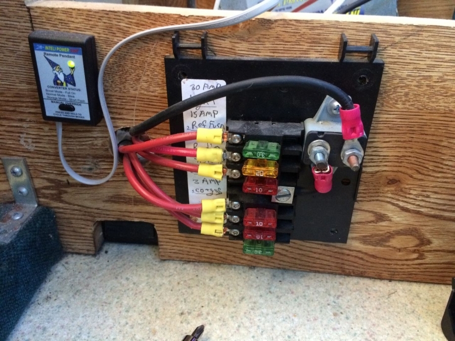
I don't have any "after" photos, because my buddy had to leave in a hurry (I hope he will take some and send them to me - if so I will post them), but when we re-did this we turned the charger over, and also wired it according to the instructions (which is how it seems logical to me anyway). i.e. wire from battery to positive bus, a positive wire from bus to the charger, and another wire from the pos. bus to the 12-volt fuse block (and a third one from the pos. bus to the solar controller). These new wires were all fused at or near the bus as they are smaller sizes than the battery jumper/lead wire to the bus. We used an 80 amp breaker that is also rated as a switch for the run to the 12-volt panel, so the panel can be "shut off."
|
|
|
|
|
03-16-2015, 04:36 PM
|
#17
|
|
Senior Member
Join Date: Jan 2013
Location: Lake Tahoe
Posts: 216
|
Re: Does alternator know how many amps to send to the Batter
Looks a lot like mine except I have a Power Source Dual Voltage PC-45. Guacho? Good reminder, I have no fuse at the battery to distribution point either.
So will 2 #8 wires equal one #6 as recommended by Sure Power?
__________________
1996 Ford EB 2 wheel drive 460
|
|
|
|
|
03-16-2015, 05:22 PM
|
#18
|
|
Site Team
Join Date: May 2007
Location: Turlock Ca
Posts: 10,409
|
Re: Does alternator know how many amps to send to the Batter
More connectors to go wrong. Why not just run a piece of #4 copper back there and be done with it? How many feet are you going to run?
__________________
2006 Ford 6.0PSD EB-50/E-PH SMB 4X4 Rock Crawler Trailer
Sportsmobile 4X4 Adventures.......... On and off road adventures
|
|
|
|
|
03-16-2015, 05:35 PM
|
#19
|
|
Senior Member
Join Date: Jan 2013
Location: Lake Tahoe
Posts: 216
|
Re: Does alternator know how many amps to send to the Batter
Quote:
|
Originally Posted by daveb
More connectors to go wrong. Why not just run a piece of #4 copper back there and be done with it? How many feet are you going to run?
|
Looks like it just under 20 feet, back, over, down, back, up. I am on Amazon etc right now. 20 foot jumper cables with #2 wire is less than just one run of 20' of #2 wire. Seems nuts so I am still searching. I am looking to run this in a safer place than the original run by the exhaust manifold. Worth the money to have less connectors like you said.
__________________
1996 Ford EB 2 wheel drive 460
|
|
|
|
|
03-16-2015, 05:57 PM
|
#20
|
|
Senior Member
Join Date: Feb 2012
Posts: 879
|
Re: Does alternator know how many amps to send to the Batter
I agree - I would just do a new wire with good connections (and proper fusing).
I like to use Ancor marine tinned/stranded cable. I have found reasonable prices for what you get on Amazon (search "Ancor cable"). I have Prime so watched the various colors/sizes/lengths and was able to make some scores (their pricing makes it like buying airline tickets...). It's not cheap though. But then I think about the van burning down and it doesn't seem so bad! Plus, boats make vans look cheap  (I guess airplanes make boats look cheap, but I have never gotten into those...)
If you are looking at the various Amazon Ancor cable, do check varying sizes/lengths (and even colors if you are willing to do a non-standard color installation). As I said, some "odd" deals do pop up. (What I mean is that a specific size/color/length will suddenly be much cheaper than usual for a short period of time.)
I don't know where you are, but I have a big crimper and could potentially make/send you a cable, if your setup will allow you to run a wire that already has the lugs on both ends. I use the FTZ lugs which I buy from either Fisheries Supply or GeniuneDealz. If you were going to use #6 wire, I have a pretty good stock of that (but I would use something larger, myself).
The Ancor is rated at 105ºC (not sure about welding or jumper cable) so you can use that for the ampacity table. If you have a specific wire run length/size/etc. I can look it up for you if you like.
My previous SMB was an aisle layout (close to an RB-31 although not exactly) and the "electrical compartment" was in the aft end of the gaucho base. Since my buddy elected not to replace the alternator wire (yet), I'm not sure how SMB ran it (I saw where it left the separator and then it came out of a hole in the wall by the fuel filler). On other E-based RV's I have checked, it runs down on the driver's side of the steering column dealie (ahead of the firewall), and then along the driver's side frame rail (under the rig) and then up through a hole in the floor near the batteries. I suppose there are a few possible ways.
My SMB originally had a huge hole in the floor (~3" in diameter) which was a sort of "drain" for the flooded house battery box. Oddly, the negative wire going to a chassis ground also went out through this hole and to the frame, making it very hard to mouse-proof. I removed that wire and ran an interior chassis ground to one of the couch bolts (which tested as grounded). Then I blocked off that hole in the floor. The original battery venting setup was a bit jury rigged looking (PVC pipes and ribbed hoses jammed into a hole in the wall panelling near a grate in the van wall).
****
Even though this doesn't specifically address the charging wire from the alternator, here is a (horrible, partial) photo of the new setup in the '97 SMB.
Apologies that this is the worst photo ever. I set out to take a nice series of "after" photos of the new setup, but my buddy was in such a hurry to head out (needed to get home all of a sudden due to circumstances) that he said he'd rather just send me photos later. So this one photo (taken peering under the partially lifted couch base cushion) is all I have for now. You can see the added battery (we replaced battery #1 and added a battery #2 so they are both same age/size/etc. (Lifeline GPL 31XT). Off to the left/rear is the new Blue Sea fuse block, and just below/right of that is the positive bus. Then near the right front of the left compartment (which you can barely see) is the shunt for the battery monitor and the negative bus. Solar controller and 110 charger (110 charger is original, just reinstalled) are out of photo to left in same compartment.
The red #6 wire running along the left side of the battery, is a wire supplying the 12-volt fuse block. It comes (unseen) from the positive bus out to an 80 amp switch-rated breaker that is just inside the couch door (so it can be reached/used by simply opening the couch door, whereas the compartment with the fuse block needs the couch base lifted to access it). Where you can see it here it is running from the breaker back to the fuse block to supply power to it.
There is normally a cover on the battery box, but it was removed for the photo.
Maybe more than you wanted to know (and nearly invisible in the photo... sigh).

|
|
|
|
|
|
 Posting Rules
|
You may not post new threads
You may not post replies
You may not post attachments
You may not edit your posts
HTML code is Off
|
|
|
|
 » Recent Threads
 |
|
|
|
|
|
|
|
|
|
|
|
|
|
|
|
|
|
|
|
|
|
|
|
|
|
|
|
|
|
|
|
|
|


 Sportsmobile (AKA Money Pit)
 Linear Mode