Ok, so I have been recommending the KISAE DMT-1230 /1250 DC to DC Charger for a while now. If you are looking for a way to turn your existing alternator into a 3-stage charger, or if you need to support Lithium, then this unit may be of something of interest. It has an added benefit of also being an MPPT Solar controller. If just starting out, it becomes a very cost-efficient solution for charging from solar & alternator. There were two things that generally held me back from installing one myself. The DMT-1250 (50 Amp Version) was not out and I had a Solar Controller, a nice solar controller at that. Well this year the DMT-1250 came out, so I thought I would take a hard look at it. My place of purchase was Don Rowe.com, they are relatively close to me, have good prices and service.
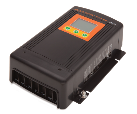
I purchased the KISAE-DMT-Abso -50A -DC to DC Battery Charger
The KISAE Abso 25ft Battery Temperature Sensor

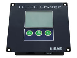
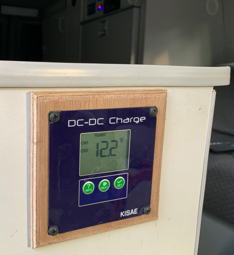
And the KISAE DMTRM1201 Remote Panel. It has identical features of the inbuilt panel; my installation would make visibility of that impossible.
First, a little bit about the unit. The KISAE DMT-1250 is a fully automatic multistage, multi input charger. It can charge house battery from an alternator connected to a starting battery, or via solar panels when not driving. The solar controller is an MPPT controller capable of 500* watts of solar panels, the panel input range can be between 14.5 and 45 Volts. The default setting is for the solar input, but it will automatically switch over to the alternator when the starting battery voltage is above 13.2 volts.
Now once the switching to alternator, the unit will continue to monitor the starting battery voltage (at the DMT-1250). After 3 mins of charging the unit will pause (5 secs) and check the voltage again with no load, if the voltage is above 12.8 volts it will continue, if below 12.8 it will revert to solar mode. If during this three-minute period the voltage drops below 11.5, the unit will start to cutback the output of the charger. If the unit would drop below 10.5 (no load) it will shut down the unit.
One can set the unit to an optional low start up voltage of 12.3 volts instead of 13.2, this is done using a manual override setting in the setup parameters, or by using the external start terminal. If one wants the option of using the low start up voltage, I suggest a SPST switch between the start terminal and an ignition terminal that is hot in run. The external start terminal should have a least a 1-amp fuse.
The DMT-1250 supports 5 different battery types, GEL, AGM, Flooded, Lithium, and Program (custom settings). It should be noted that for batteries like Lifeline, you are suggested to use the Flooded settings.
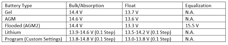
While flooded is close to my lifeline battery specs, I will choose Program or Custom Settings, and program the Bulk/Absorption to 14.3 and the Float to 13.3, and while you can perform a conditioning charge on Lifeline, like Equalization, I would not set that up with this unit, better to perform that with shore charger.
The next thing you can change is the mode, do you want Mode3 (3-stage charger) or Mode 2 (2-Stage charger). The default is Mode 3, it contains a Bulk (constant current), when it reaches about 80% of capacity it will transfer to Absorption (constant voltage with tapered current), when absorption is complete, we transfer to the float stage. The DMT-1250 will give you three setting for float current, if you have devices that are normally running you can adjust the current higher. If the voltage of the battery falls below 12.9 (lead acid) 0r 13.3 (lithium), we go back to bulk phase.
Mode 2 is the same except when we get to the float transition point, we turn off the charger. Again, if the battery falls below 12.9 (lead acid) 0r 13.3 (lithium), we go back to bulk phase.
Another feature of the DMT-1250 is that it supports a remote battery temperature sensor. If youve ever seen a battery voltage charging chart you would see that the values change as temperature does. The 14.3 for absorption and 13.3 for float are based on a temperature of 77°F or 25°C. The voltages will inversely move as the temperature goes up or down from those points. For each degree below 25°C the setpoint for the charger voltages will go up 0.027V)/ °C (flooded) or 0.021V / °C(AGM), for each degree above 25°C the setpoint for the charger voltages will go down 0.027V)/ °C (flooded) or 0.021V / °C(AGM). So, it is possible at 0°F to see your absorption voltage at well above 15 Volts.
If you choose not to purchase the additional sensor, you can switch the between three setting Nor (41 86) °F no compensation, Lo below 41°F +0.675V(flooded) +0.525V(AGM), and Hi above 86°F -0.270V(flooded) -0.210(AGM).
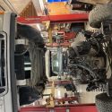
Now, moving to the install, removing the bottom protection plate, allows you access to all the hook-up inputs.
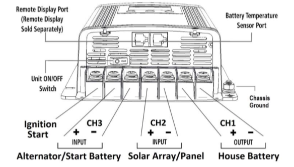
All the cable connections attach with screws, they dont specify size I suspect M6 and I used ¼ ring terminals for all the connections. Towards the top you have remote port and temperature sensor port.
The torque spec is 35-45 lb-in. The most problematic feature I find is the location of the on off switch, once installed this switch will most likely be very hard to get to, so make sure you turn it on when complete. I would like to see an external connection made available so that the on/off feature could be moved, maybe even done thru the remote.
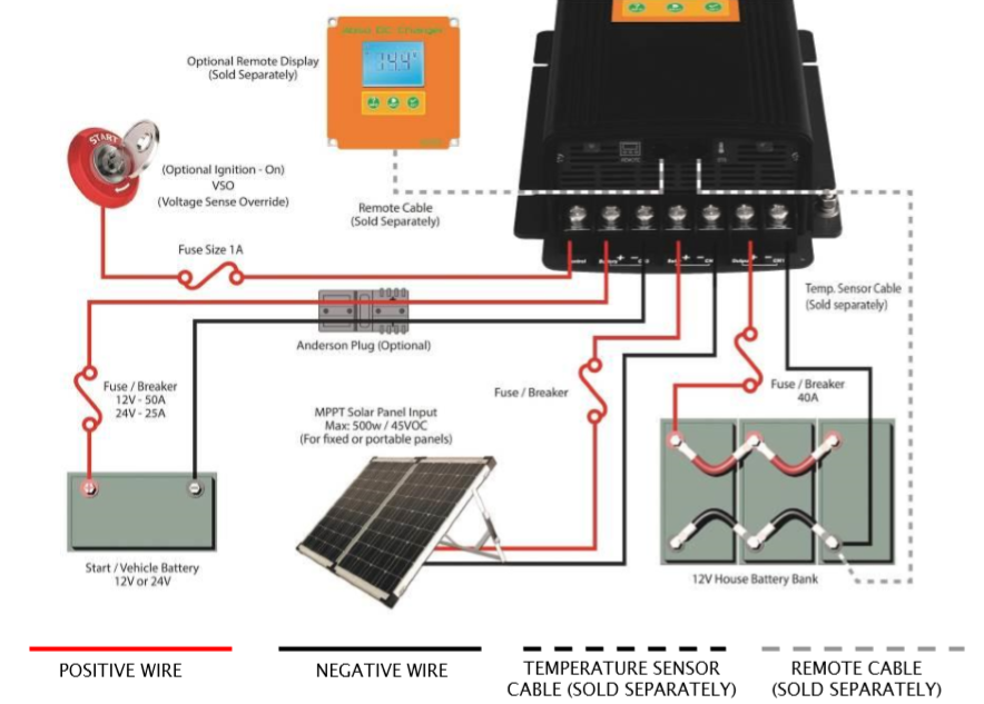
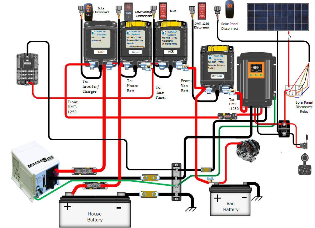
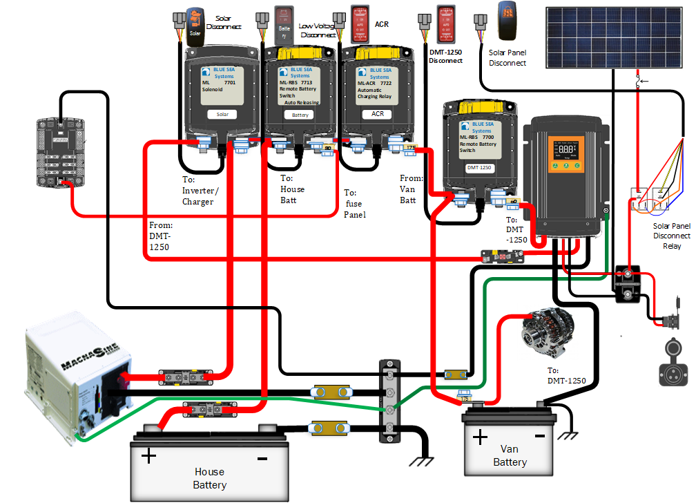
The diagram below is the basic installation provided by KISAE, you have power & ground from the output of the DMT-1250 to the House Battery. Solar power & ground goes from DMT-1250 to Panels like and other controller, the difference here is we have an additional power & ground as a input from the Vans Alternator/Starting Battery. This diagram also shows the hook up of the optional Voltage Sense Override. The manual also gives information for fusing and wire size (the wires size is in metric, so you will most likely need to convert) I used 2 AWG fron the starter to the input of the KISAE DMT1250. The output of the solar used the existing cable there that were 4 AWG. My Solar cables are 8 AWG.
This should be straight forward, but first we need to look at my existing layout below. As you can see, I have a couple of additional BlueSea Battery Switches on my rig. I have the traditional 7622 ACR between starting battery and house battery. The difference is that I have a Remote Battery switch between the ACR and the House Battery. The main purpose of the RBS 7713 is for a low voltage disconnect circuit; the details are not in the diagram below. To the left of that I have a Blue Sea Solenoid switch between my house battery and the solar output. I had this switch laying around, so I installed to easily disable solar. Later, I decided it was easier to disable solar by putting a relay between solar input and panel. These three devices also make a nice busbar, but you will notice that things are placed for a reason. If RBS 7713 disconnects it will disconnect the house battery from fuse panel distribution, thus why it is used as a low voltage disconnect. You can see, that the fuse panel is still connected to the house side of the ACR, so by having the ACR connected I can have the alternator/starting battery provide power to the house fuse panel. All this time solar can still be connected to the house battery, so I use this option sometimes while driving to make sure I can top off the house battery with a 3-stage charger.
Moving to the standard DMT-1250 install I am losing a couple of options. I would no longer be able to charge starting battery with solar or shore power, and I would lose a jumpstart aid from the house battery if needed. In the 15 years I have owned the rig I have yet to use the house to jumpstart the van battery. I also am not a big proponent of always topping off the starter with solar or shore power.
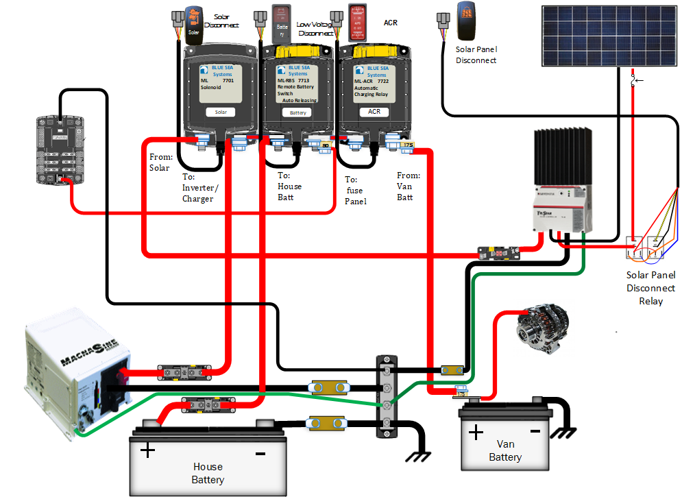
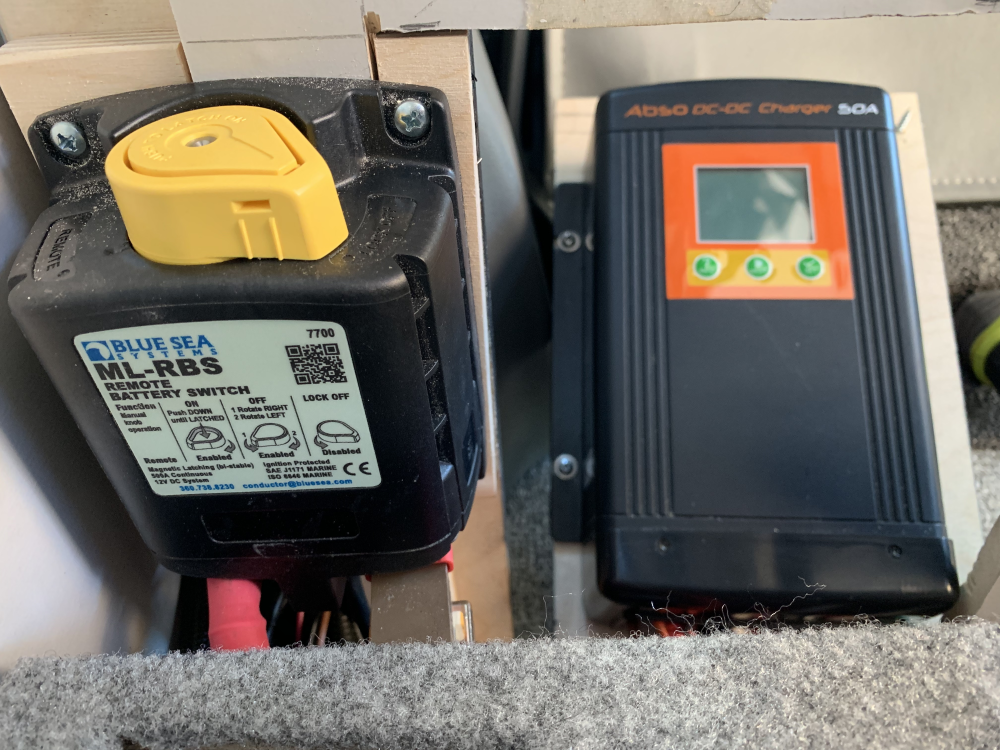
I do like to design for redundancy, and now that I have a charger takes solar and alternator power, I have one point of failure taking out to charging options. I wanted to see if I could keep the ACR. My first thought was to move the solar disconnect battery switch over to the input of the DMT-1250. In the end I decided to add another battery switch, this time using the Blue Sea 7701, like the 7700 except it has the manual override knob.
Now I can disable the DMT-1250 input and allow solar of shore power to charge my starter by putting the ACR back into auto mode. This is essentially how it ran with the previous solar controller. By leaving the solar output disconnect I have a way to totally isolate the DMT-1250 from the system, force the ACR to connect for jumpstart purposes. While this looks more complicated adding the new switch was easier than moving and reconnecting things (I lose my bus bar)
Ok, so this worked when tested but I ran into a small problem, the grounds for the three inputs to the DMT-1250 are internally bonded together. I had tied the ground for the alternator input back to the same house ground bus bar as the output, that bus bar is tied to frame ground. The problem that came up was with the shunt I have on the output of the DMT-1250. I was reading about a third of the current, as it most of the current flow was on the larger input cable. I did contact KISAE and was given an explanation and the following diagram
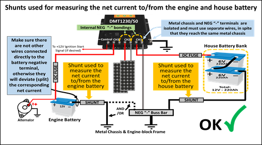
This did not exactly cover my usage, but I decide to make a change, (the change on paper was much easier than the actual wiring mod)
I ran the ground from the alternator input straight back to the starting battery, I also removed a large similar size cable that was from the battery to the frame. The original battery ground was left. With this change I found that output current was now fully flowing thru the shunt resister.
I also purchased the remote, the location of the unit will not be easy to get at, especially for setup programing. It hooks up with a provided RJ12 cable (6 pin, they use 4 wires). Luckily for me the same kind of cable was left in place from the previous unit. I hooked it up and it worked and that was one less cable to run. My biggest complaint on the remote is the location of the jack input. It makes a tougher install then it should be.
The next thing I added was the temperature sensor cable, unfortunately this can only be done by dropping my 4D battery. My old solar controller had what I think was the same sensor, it was 2 wires while the new one was in a RJ12 connector. I would have looked more into using the old one if I hadnt already decided I was replacing the temp sensor for my magnum inverter, it has always been a little of when compared to the other temp sensor installed. All went well, I shortened the cable and installed a new jack. After installing it I went to the temperature sensor location in the setup, much to my dismay the program did not change at all. No indication that the sensor was hooked up at all. OK, so this was my bad, I should have checked it out before shortening the cable. It is not like havent done this before. Luckily, I had the email for support and asked what to expect.
The Nor,Hi, LO settings are used when having no BTS plugged into the unit, and are ignored when using the optional temperature sensor KISAE # BTS10K. With the BTS plugged, the unit automatically starts using it in spite of the Nor, Hi, LO settings. You can check if the BTS is working by varying its temperature (e.g. by immersing it a cold and hot-water/heat-gun). It is an NTC resistor with about 10 KOhms @ 25°C.
Unfortunately, the sensor is already installed on the battery, not much chance that is getting dropped again. I will just have to monitor the voltage output with the battery temperature readings from other sensors. I think that is my biggest complaint, while the sensor will be able to do its job 100% without being visible to the user, having a temp reading on the display just seems like a small ask.
I also worked the technical resource for any information on the protocol between the unit and remote, I was looking to tap into that to see if I could read any info directly into a computer. While he did give me some info, he did not have nor could he provide a documentation to pinout and packet information. For now, any activity of reading from their controller will be put on the back burner. I did decide to surround the inputs & outputs with current and voltage probes.
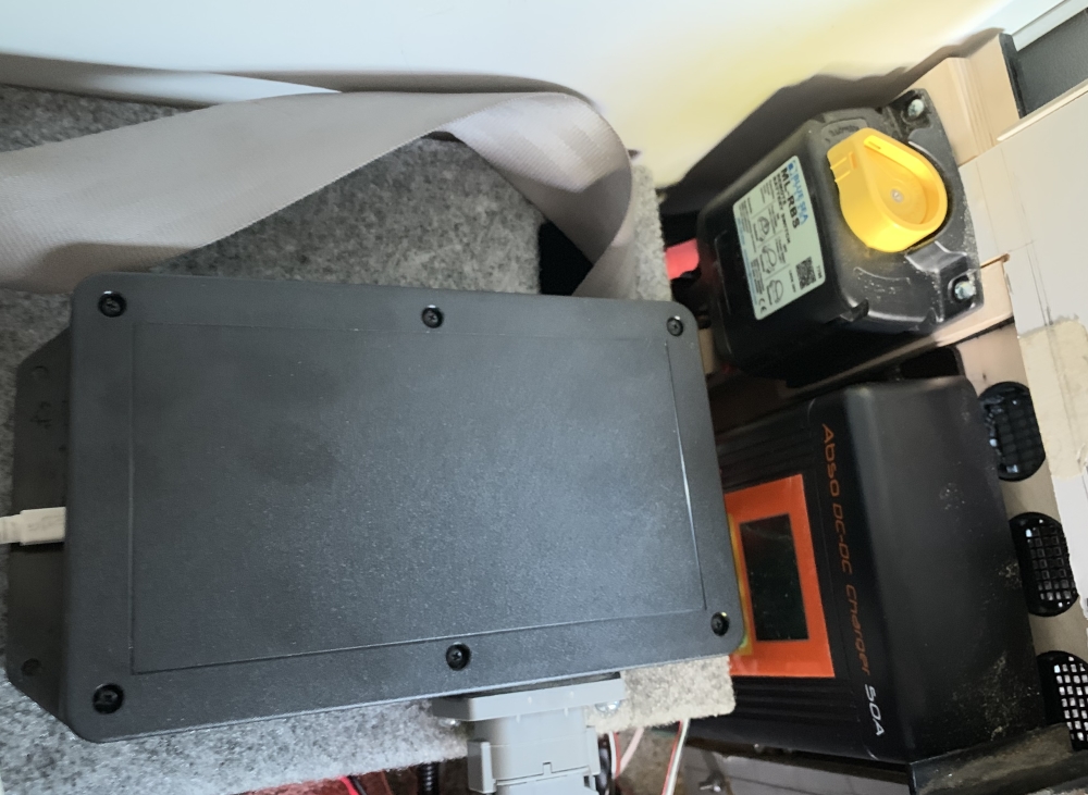
The below box holds 5 of the six devices reading the DMT-1250, Alternator Voltage, Alternator input current, Solar Panel Voltage, Solar Panel Current, DMT-1250 Output Voltage, and DMT-1250 Output Current. The other two devices in the box are the Hub interface, and my Propane Gauge Sensor. The
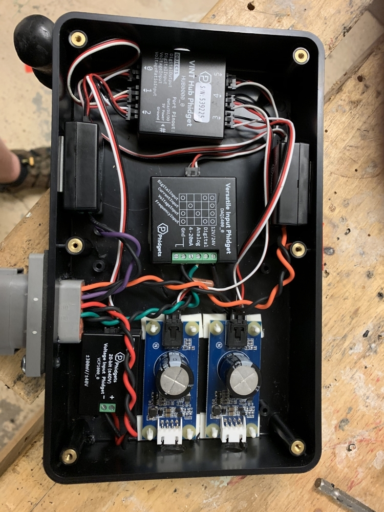
The DC transducers are a set of hall-effect based sensors that can measure the amount of current flowing through a wire simply by threading the wire through the sensor's window.

The DMT -1250 is mounted on the side of the Gaucho behind the driver seat, it was slightly wider than the previous Solar Controller I had there. I added some vent holes as the unit is under the gaucho.
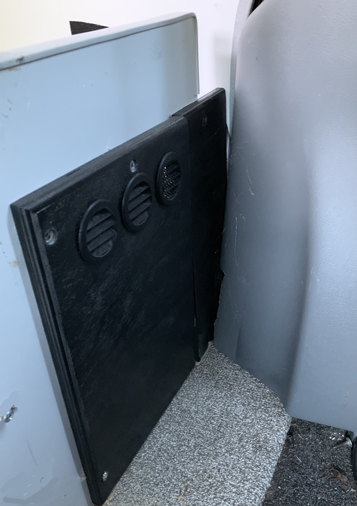
The business side of things
In the down position so I can have access to wiring.
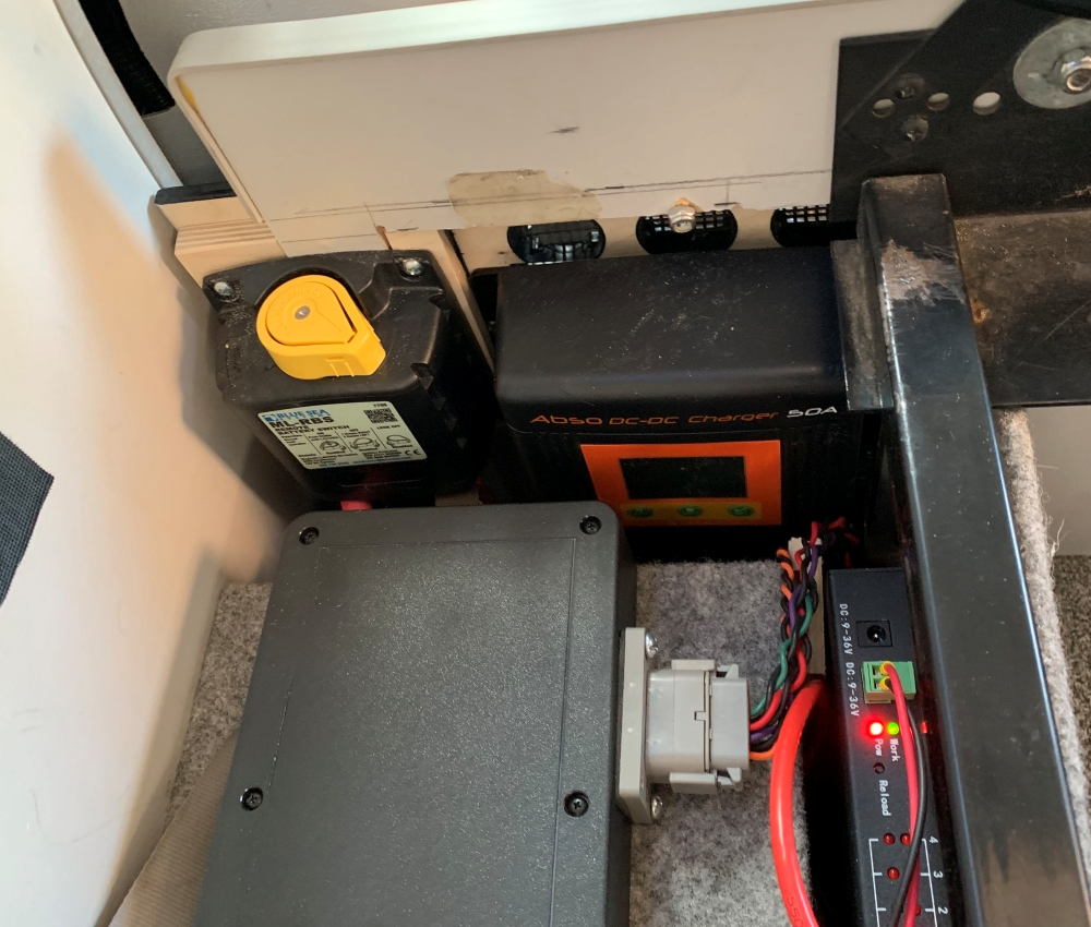
The business side, the disconnect to the left, you can also see the monitoring box.
The last thing was to mount the remote. While disappointed I couldnt get data from the remote (it still may be possible) I need the remote to program the unit. I guess I could have tried it directly, but it is hard to get at. As I said earlier the cable was the same as my previous controller, so I used the same cable. The hole size was not so I needed to modify the mounting location.
Programing the DMT-1250 can be somewhat of a challenge. I have worked with a lot of one button controllers in my career, but even I found this somewhat confusing.
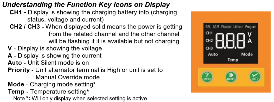
The Appendix section of the manual has a pretty good walk through of programming options.
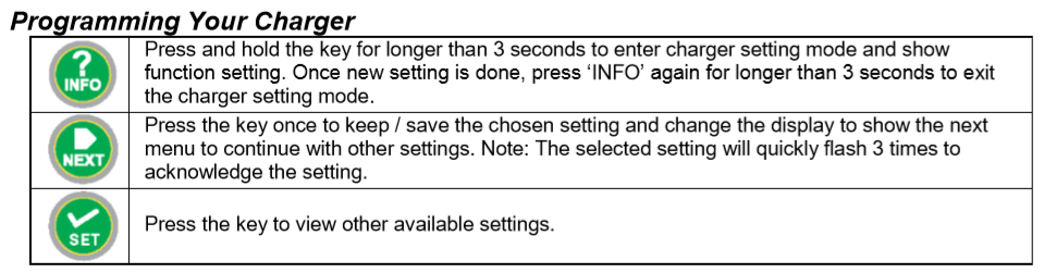
Ok, so I took if for its first run on the alternator and used my data logging program that was modified for the DMT-1250. MY first problem was I forgot to take screen shots until I was halfway through the trip. The bigger problem I had was that the ground path was coming back to haunt me, With the alternator input causing higher current output, the difference in the readings were substantial. That only results in a logging issue, not a performance issue. The second thing I noticed was the DMT-1250 goes through a test every three minutes, it goes idle and checks the starting battery voltage to see if the current draw is too much. I did not account for the idle state, so again a logging issue not a performance issue. The thing that did catch my eye was the shutdown state. It appears that when I turn off the van, obviously the starting battery will drop below turn off threshold, but it appears that it takes a little time for this to occur, almost like it is tied to that 3 min check. So, while the van is off, we can have the charger pulling 50 amps out of the starting battery for up to 3 mins or so.
This results in the starting battery getting left at 12.6 volts after the van was turned off.
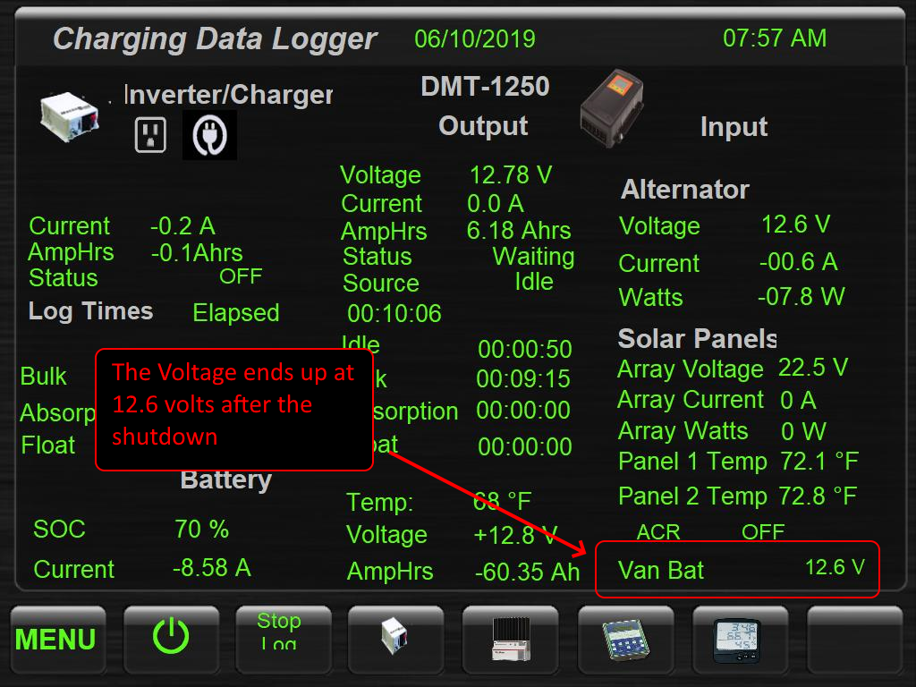
This is a repeatable action, I will say that the issue is less concerning in float or absorption phase with lower current draw, the lower the current draw at turn off the less it could draw down the starter. Remember most ACRs are designed to disconnect as soon as the unit drops below 12.8.
So, this may not be a huge issue, but I cant just let it go. For me the problem could be non-existent, I can just disconnect the input, the switch is in the overhead console. It would be nice if I did not have to remember to hit the switch when I turned off the van. I decided I could install a DEI 452T door lock pulse generator and automatically connect the alternator/starter to the DMT-1250 when the van is running and would disconnect when the van was turned off. This mod will allow the manual switch to still work and provide the automation I desire.
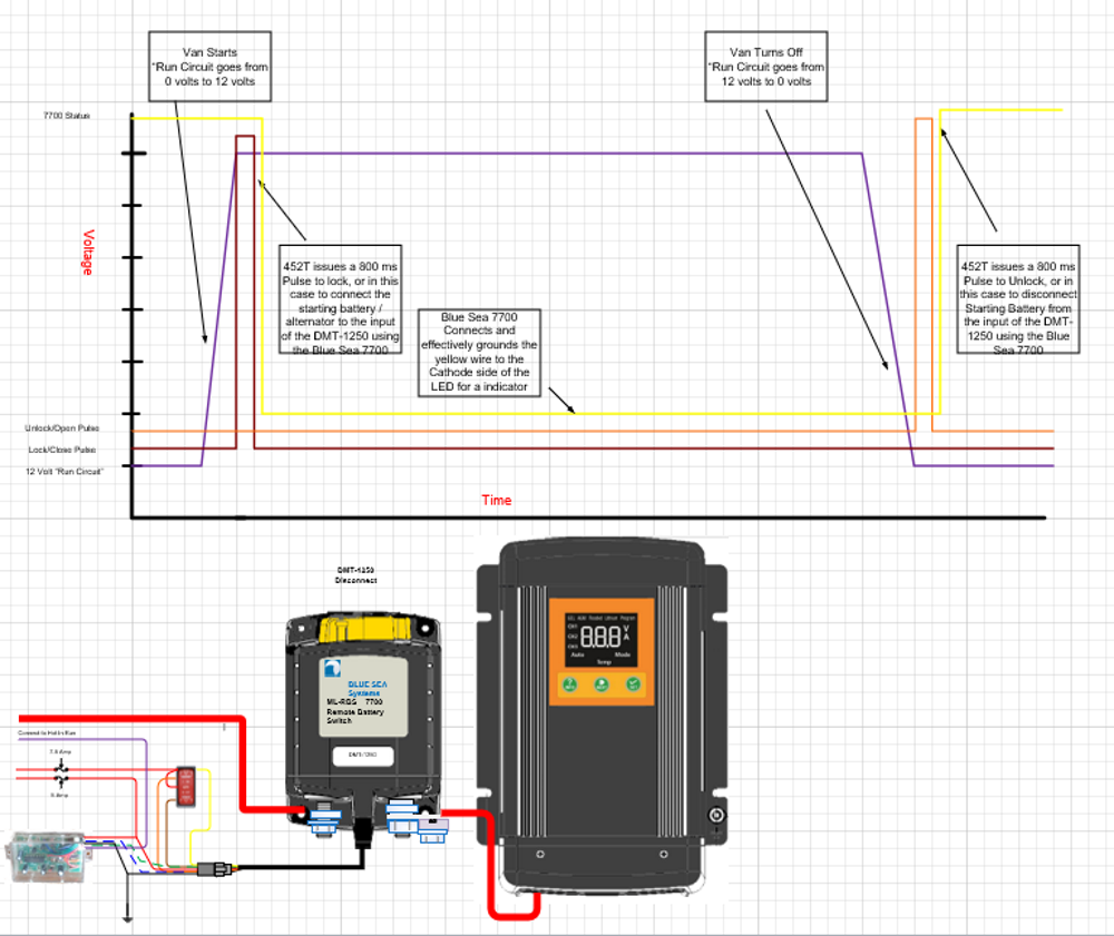
In retrospect, had I been thinking of this in the beginning I would have chosen another auto releasing switch the Bluesea 7713, then I could use the run circuit directly to connect and disconnect. Another lower budget solution would be Bluesea 7615, this unit can be configured in multi ways, but one is a simple solenoid, again it could be connected & disconnected with the run circuit. This unit is in the same package as the popular Bluesea 7610 & 7611 ACRs.
While I have confidence that my mod will work, the high temperatures and having family in town has prevented me from completing that part of the installation. I was taking a day trip to the coast and decided it would be a good time to log some data on the performance. I have made a couple of changes to my logging program; I even automatically take a screen shot when the SOC value changes. One of the things you will see is a pretty high current consumption, I have my stereo / infotainment system running, and at this time of year the Starcool is running at least low speed. This is all running on the house side, and part of the reason I waited for the 50-amp unit to be ready. This is a combination of charging off the alternator and solar
KISAE DMT 1250 day trip
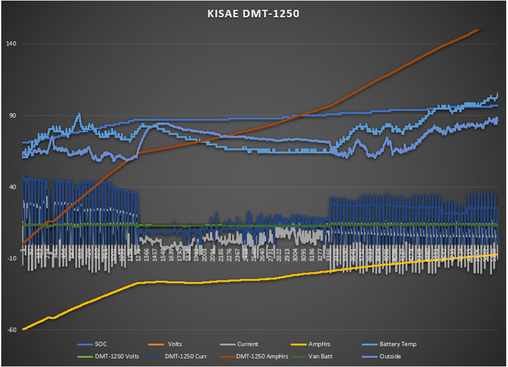
While the graph is tedious you can see the charge coming out of the DMT-1250, it has that three min window when it goes idle so you can see a drop-in output for about 15 secs. The gray line behind it that tracking is what is going into the battery. The middle of the graph shows a lower output because we are on parked and on solar power.
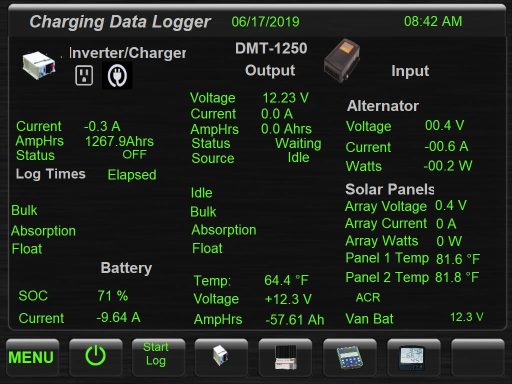
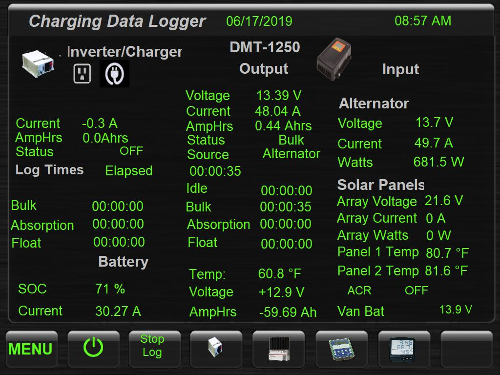
Below we see a snapshot before I started the log program. Battery is at 71% SOC and is -57.61 Amp-hrs.
After starting the van and logger we see that DMT-1250 is putting out a healthy 48.04 Amps
We arrive at the beach about 1 hours 42 minutes later. By now the DMT-1250 is in the absorption phase and we have increased the SOC to 87%

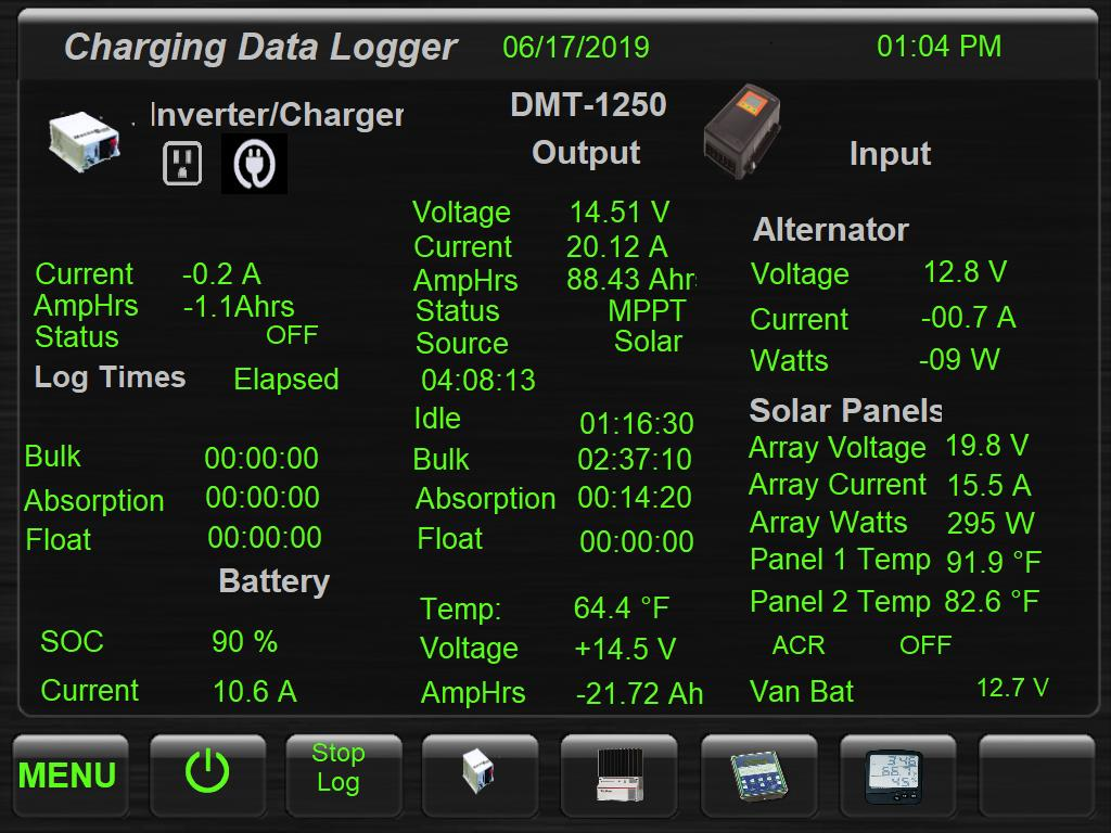
The DMT-1250 the switched over to solar mode. A good snapshot sometime later we can see solar has brought the SOC up to 90%. At this time the normal coastal cloud cover lifted, and we are getting a robust 295 watts out of the panels.
Here we are starting back up to go home. The SOC is at 92%, 8 amps going into the battery.

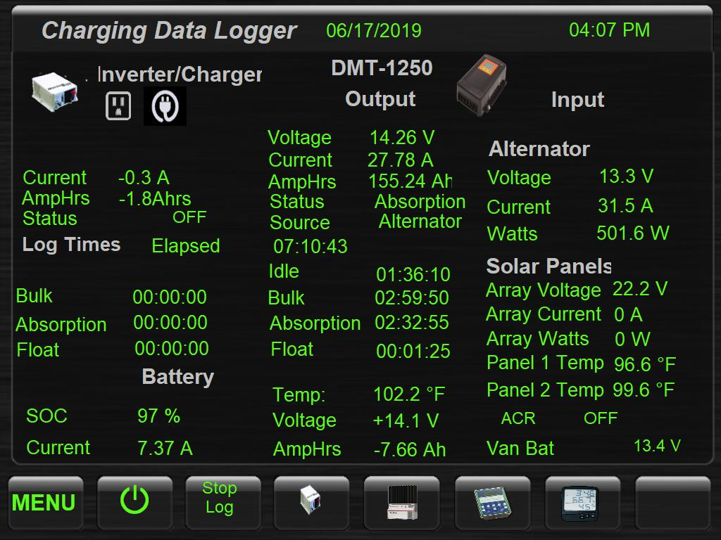
End of the trip. Total time logged 7:10:43. Of that we spent about 3 Hrs. in bulk and the remainder in absorption. I do believe my Idle numbers are high, as I still have some programing changes to make, the reported time in float is also an error in programing. We ended with 97% SOC
-greg


 Tan Hot Dog
 PhoTo
PhoTo

 2008 GMC 3500 SMB

 Linear Mode