A member asked in another thread, if there was a golden rule for fuse rating, relative to load or max current. My simple answer would be to look at the documentation of the product you are installing. Many items have a pretty good recommendation of wire size and fusing. If it doesnt directly discuss wire size or fuse rating it should still have some info on things you need to know to make those choices.
The second rule would be to take the product rating and multiply by 125%, this would become our minimum fuse rating, the maximum fuse rating is the ampacity of the wire you chose with the proper derating. The fuse selection should be in the middle if possible. Some products my dictate a specific fuse size, if that size is above your wire ampacity then you need to choose larger wire.
I thought we could go little deeper cover a couple of common items to wire and fuse. First you need to come to some standard that you want to adhere to. My van was RIVA certified, I was not impressed with the overall electrical system, so I looked elsewhere. One that is highly publicized and like an RV is ABYC (The American Boat & Yacht Council) Standards. It is also relevant because so many of us use Blue Sea Products and of course their Circuit Wizard. All of those products adhere to t ABYC standard. The standard that we would use the most is ABYC E-11 AC AND DC ELECTRICAL SYSTEMS ON BOATS, many excerpts and tables shown below may come from a 2008 version
http://www.blackfinforums.com/sites/.../abyc-e-11.pdf that can be found on the web. For an up to date version you need to go to
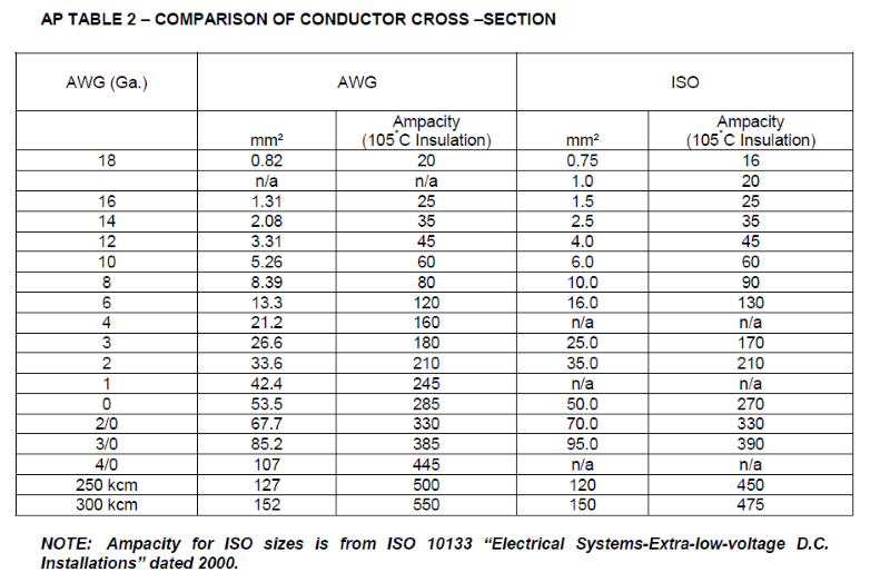
https://abycinc.org/store/ViewProduct.aspx?id=12011421 . It is also good to note there are about 5 different wire ampacity standards ABYC, ISO, JASO, NEC and AS/NZS. The NEC and AS/NZS standards are primarily for AC and produce lower values. ABYC and JASO track closely while ISO is less but higher than the NEC and AS/NZS. It is good to make sure the wire you are using matches the calculator or chart you are using.
If we take a commonly used item such as the MAXXAIR Deluxe Fan. The MAXXFAN requires a minimum 12 Volt DC, 5-amp service. Confirm that the circuit you intend to use will accommodate the additional load. Use the proper gauge stranded wire for electrical connections. Looking at the Blue Sea calculator we see at 12 volts 5- amps 20-foot, 10% drop, 105°wire, no other derating we get 18 awg wire as the recommendation. 18 awg will have an ampacity of 20-amps in this case. ABYC has a minimum control wire standard that calls out for a minimum of 16 awg, this is more for strength than current caring capacity, looking at 16 awg wire we see it has an ampacity of 25-amps. So are min fuse size would be 5 x 125% or 6.25-amps and the high end would 25-amps of the recommended 16 awg wire, it seems a 7.5-amp to 10-amp fuse would be just fine. The other thing I would look at is what size wires does the Maxxair fan come with? If we were to find that they were 18-awg pigtails I would use 20-amp of the connecting wire as my wire ampacity target. Still as 7.5-amp to 10-amp fuse would work nicely here.
Let us take a simple fuse block such as Blue Sea ST Blade Fuse Block. I ve chosen the 5031 but the 6 circuit, and 4 circuit models have the same rating. Maximum Amperage is 100A per Block and 30A per circuit. They have a maximum voltage of 32 volts and no minimum.
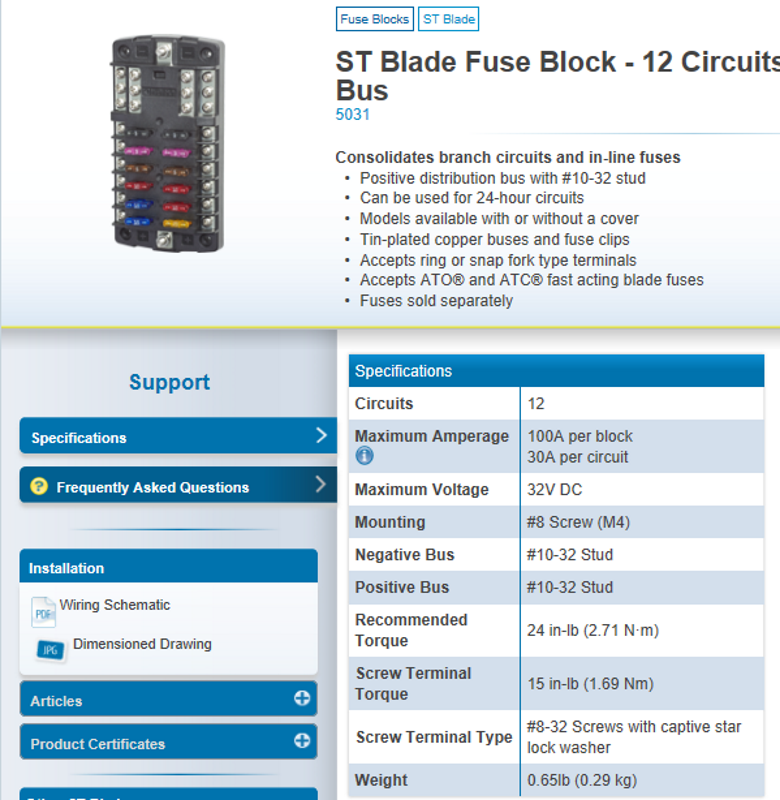
Digging a little further we see a wiring schematic

The application note tells us that suitable main circuit protection of not more than 125A rating should be provided ahead of this device with an interrupt current rating consistent with battery capacity. So here they are specifying the maximum fuse size and AIC rating. Interrupt rating (AIC) is defined as the fault current that a device, normally a fuse or circuit breaker is capable of breaking without damage.
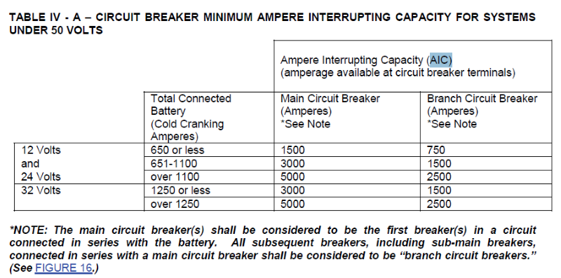
This brings us to another topic; Main Circuit versus Branch Circuit. Main circuit breakers) shall be the first breakers in a circuit connected in series with the battery. All subsequent breakers, including sub-main breakers, connected in series with a main circuit breaker shall be branch circuit breakers. The below table gives us an idea of what AIC we need to use based on CCA of the battery bank we have.
An update for 2018 ABYC E-11 AC AND DC ELECTRICAL SYSTEMS ON BOATS
"11.10.1.2.3 For batteries or battery banks with a CCA rating greater than 2200 CCA, or 500-amp hours, battery overcurrent protection shall have a minimum ampere interrupting capacity (AIC) rating at least as great as the battery manufacturers short circuit rating or be rated at a minimum of 20kA at 125 VDC or higher."
For a comparison Lifeline 4D batteries have a CCA of 1100, two 4D batteries would still be under the new rating. Of course, it is something to look at, a single 4D lifeline would require a fuse or breaker with a minimum AIC of 3000.
Lets look at the standard ATO/ATC fuse. As we can see it list the amperage the fuse supports in this case 5A and an interrupt capacity of 1000A. If we had this fuse between a 4D battery with a CCA of 1100A, it would not adhere to the AIC rule.
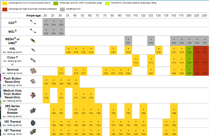
Blue Sea fuses and AIC ratings below
1000 (AIC) MAXI Fuse, ATO/ATC fuse, ATM fuse, easyID fuse.
2000(AIC) MRBF terminal Fuse @58V, AMI / MIDI Fuse @ 32V
5000(AIC) MRBF terminal Fuse @32V, AMI / MIDI Fuse @ 16V
6000(AIC) ANL Fuse
10,000(AIC) MRBF terminal Fuse @14V
20,000(AIC) Class T fuse 2000A @ 125V DC
Some Blue Sea Circuit Breakers and AIC ratings below
1500(AIC) 187-Series Circuit Breaker@42V
2500(AIC) Push Button Reset-Only @28 volts
3000(AIC) Push Button Reset-Only @14.7 volts, Medium Duty Push Button Reset Only @ 120C AC, 285-Series Circuit Breaker @ 48V, 187-Series Circuit Breaker @24V
5000(AIC) Medium Duty Push Button Reset Only @ 32V DC, 187-Series Circuit Breaker @ 12V, A-Series Flat Rocker Circuit Breaker@32V DC, C-Series Flat Rocker Circuit Breaker @32V DC
7500(AIC) A-Series Toggle Circuit Breaker@65V DC, COTS Military Grade A-Series @65V DC
You need to check the specs of each fuse or breaker, as some may change depending on size, purpose.
With a 4D battery we can choose am MRBF fuse, or AMI/MIDI fuse (5000 AIC) the input fuse of the fuse block. A 285 or 187 series breaker (3000 AIC) would also work. If you have a breaker that does not meet the minimal (AIC) than you can put a fuse that does in series, between the breaker and battery.
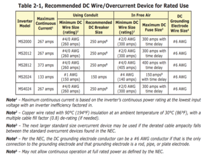
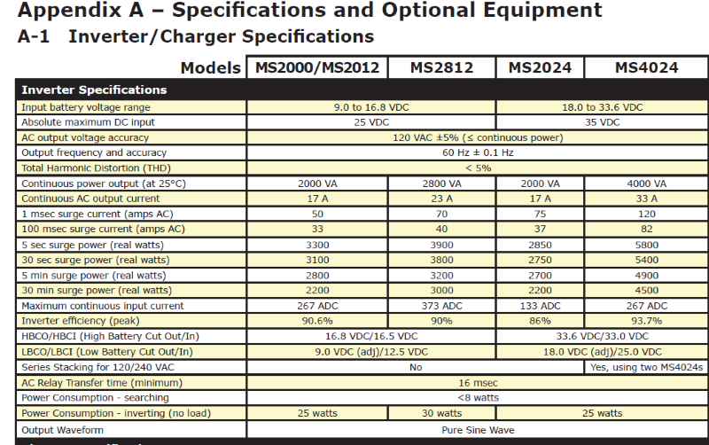
Lets look at something a little larger, like a magnum energy MS2000 Inverter/charger. If we look at the chart below, we will see a recommendation for wire size and fusing. First thing we look for is maximum continuous current, 267 amps. The first thing that might come to mind is where did they get that number from? A 2000-watt inverter would be 2000/12 = 167 amps. Looking at note1 we see that the maximum current is calculated on the lowest input voltage and inverter efficiency factored in.
Let's look at the efficiency chart below, the MS2000 is about 80% efficient at 2000 watts, so that would move are wattage for max current up to 2400 watts
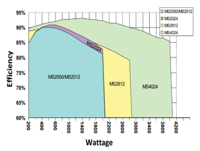
Now if we look for the operating voltage of the inverter in Appendix A below, we find that the operating voltage is listed as 9.0 to 16.8 volts. So, our lowest operating voltage is 9.0 volts, making are maximum continuous current equal to 2400 / 9 = 267 amps. That is a big difference from the quick 2000/12 answer pf 167 amps.
Other than showing I am creature that enjoys reading a good spec sheet, the point of that exercise was the you need to take voltage into that equation. The fuses don't see watts they see current, the current goes up as voltage goes down. Devices that perform conversions may have efficiencies that we need to calculate for.
Looking back at the table 2.1 we see that they recommend 4/0 awg if the cable is in conduit and 2/0 awg is in free air. While wire in the conduit does not directly increase your current needs, the temperature is increased by putting the wires in a conduit. Part of the ampacity equation is what the temperature rating of wire sheathing is. For most of our applications, our wires will be in free air and we can see the recommended size is 2/0 awg. One important thing to remember is that the derating is also needed when you bundle current carrying wire together TEMPERATURE RATING OF CONDUCTOR INSULATION NO CONDUIT WHEN UP TO THREE CURRENT CARRYING CONDUCTORS ARE BUNDLED, SHEATHED OR IN CONDUIT And while we are on this topic, I do not believe the Blue Sea Circuit Wizard correctly adjust for the wire being in a conduit .
Another thing to note is the ampacity table they are using for calculations is an NEC table for 90° wire. In this forum we generally point to the Blue Sea Calculator which is similar, but you will find slightly higher values in the marine wire supported by the ABYC standard. It is good to make sure the wire you are using matches the calculator or chart you are using.
When it comes to fuses, we see that in the conduit the maxim current of the 4/0 awg wire is 260 amps, this is below the worst case 267 amps that were calculated. Thus, you can see they recommend a 250-amp circuit breaker. So, while their wire does not meet the max current, they protect the wire with a fuse or breaker that is below both the wire and max current of the device. A resettable breaker is a good choice in a circuit that you are limited by the cable and fuse selection.
Looking at the free air solution, we see they list 2/0 awg wire and a 300 amp fuse selection. In this case the wire is rated for 300 amps and the fuse is rated for 300 amps. In a perfect world a 275-amp fuse would have been nice, but the availability in that range is usually 250 and then 300. This is also a case where using marine wire rated a 105° would give you extra comfort room, as its max ampacity would be 330 amps.
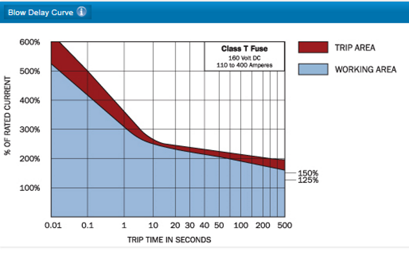
Now that we went through that we can see the general rule of thumb would be to pick a fuse that is greater than the max current of the device it is supporting but below or equal to the current capabilities of the wire. But, wait we can see in the table 2-1 again that they chose a 300-amp fuse with time delay. What does that mean and why? Well while we calculated out the max continuous current, we did not cover the surge power. As the inverter tries to handle that load when it turns on it could see an actual inrush of current that is higher than the worst-case spec. Again, if we look at appendix A, we see that they list wattage that is supported by unit from a 5 sec surge of 3300 W ,30 sec at 3100 W, 5 min at 2800W, to a 30 min surge of 2200 watts. if we check our numbers again, 3300 @ 80% efficiency; 3960 watts / 9 Volts = 440 Amps. You can see by delay curve, the fuse can handle over 200% 600-amps for a minute, 5 min at 2800 @ 80% efficiency; 3360 watts / 9 volts = 374-amps, the 8 min mark is above 150% or 450-amps. You can see why most high wattage inverters manufacturers recommend using a Class-T fuse.
Another common thing that we use on our vans is an ACR or separator, these always seem a little complicated when comes to fusing. Remember any fuse directly off the battery needs to have proper (AIC). we need to know CCA of house batteries, starting batteries and output rating of your alternator.
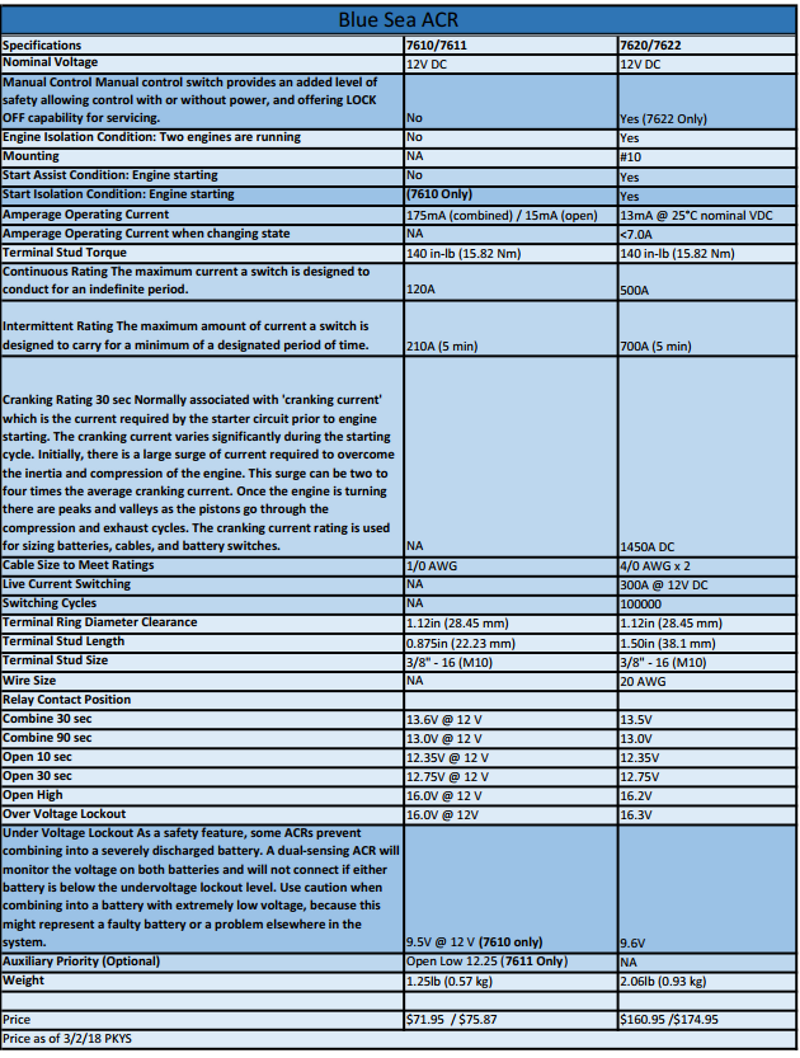
The most popular choices for new ACRs are the Blue Sea SI-series 7610 and BatteryLink 7611 along with the more robust ML-ACR 7620 & 7622. The 7610 & 7611 are very similar, both support 120-amp continuous rating 210-amp for 5 min intermittent rating. The 7610 has start isolate provision and also supports under voltage lockout. The 7611 does not have start isolate, supports auxiliary battery priority (lowers disconnect voltage from 12.75 to 12.25). The other feature the 7611 doesnt have is under voltage lockout. For those of you that have drained your house battery below 9.6 volts and have found that your ACR appeared not to work, this feature is why. If you dont like under voltage lock out the 7611 would be your choice.
If we want to move up, we can move to the ML-ACRs the 7620 or 7622. The ML stands for magnetic latch relay, once moved into position the relay does not need any power to stay in that state like a continuous power relay. Both the 7610 & 7611 are FET devices 175-mA while combined 15-mA while open. The 762X devices operate on 13-mA, but use <7.0-A when changing state. The big difference is the 762X series have a 500-amp continuous rating and a 700-amp intermittent rating. Well there is a caveat to those values, to meet them you need to have the 2X 4/0 Awg wires, while the 7610 -11 can use 1 awg wire. The 762x has way more capability, but most of us wouldnt wire it up for those capabilities.
The 7610 & 7611 are good examples of why we follow the first rule of thumb, check the product documentation.
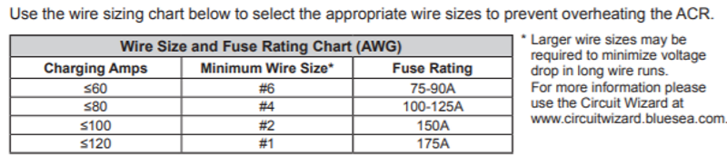
Looking at the 120-amp row we see a fuse rating of 175A, and a wire size of #1 awg. The #1 awg wire gives us an ampacity of 245 amps, #2 awg wire would have covered the 120 amps with an ampacity of 210 amps. To be honest #4 awg wire would cover with ampacity of 160, our minimum fuse rating is 150A. The line above the chart tells us why
Use the wire sizing chart below to select the appropriate wire to prevent overheating the ACR. While the smaller wire size could carry the current based on ampacity, the heat generated could cause the ACR to overheat. Remember these units have power FETs. The larger size wire would reduce temperature of the wire the same as larger wire reduces voltage drop.
The ML-series has much more capability, and a function referred to as cross connect, where you can pull starting current from the house battery if the starter is dead. This is much harder thing to fuse for, and even the ABYC guidelines allow you to not need fuses if you are using for this purpose. Having fuses doesnt not allow the unit to do this feature, just understand that the fuses may get blown.
For the ML-series I generally go back to the general rule, I have a 140 Amp alternator, 140 x 125% = 175 amps, I run #2 awg with a maximum ampacity of 210-amps. I have run 175-amp MRBF for quite a few years.
Should I put an inline fuse on the ground line? All ACRs get their power through large conductors connecting the house and starting battery banks. In the event of ACR internal circuity fault, this could allow high amperage fault current to flow from the high-power conductors to the negative reference wire capable of carrying 20-amps. A 10-amp fuse is recommended on the ground connection. And finally think about making the ground cable from your starter battery at least the same size as your starter battery to ACR cable.
Now lets look at another device, the KISAE DMT-1250. This unit will function as a DC to DC and solar charger. First rule is to look for at the documentation.
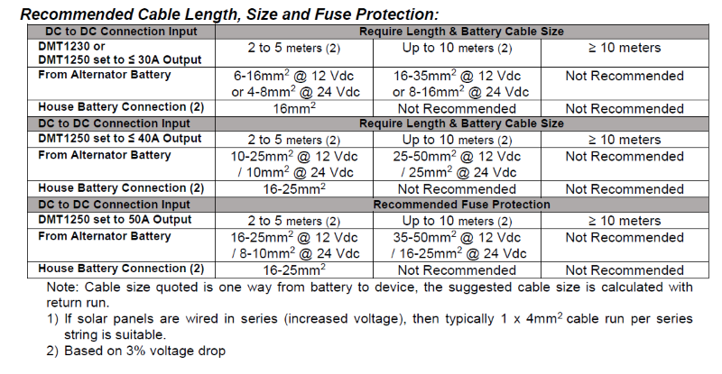
The first thing we run into is that the wire sizes are metric and specified in mm². Luckily you can find conversions online or in the ABYC E11 document you downloaded
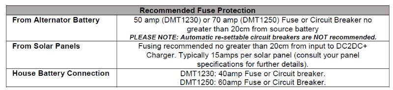
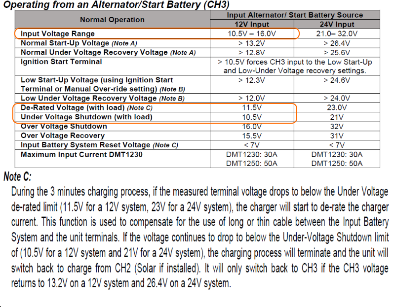
Now lets see what the operating voltages are. They are listed as 10.5 16.0V. We also have a note C that states at 11.5V it will start to de-rate the current, and completely shut down at 10.5. They did not actually reference a voltage for the 50-amp rating, so we will default to 12 volts. 12 x 50 = 660W, 660 / 11.5 = 52.2A multiply X 125% = 65.25A. They have recommended a 70-amp fuse.
For the output they did specify 50A at 12 volts for the charger output, so we can use the straight 125% of 50A and get 62.5, again here they recommend 60A
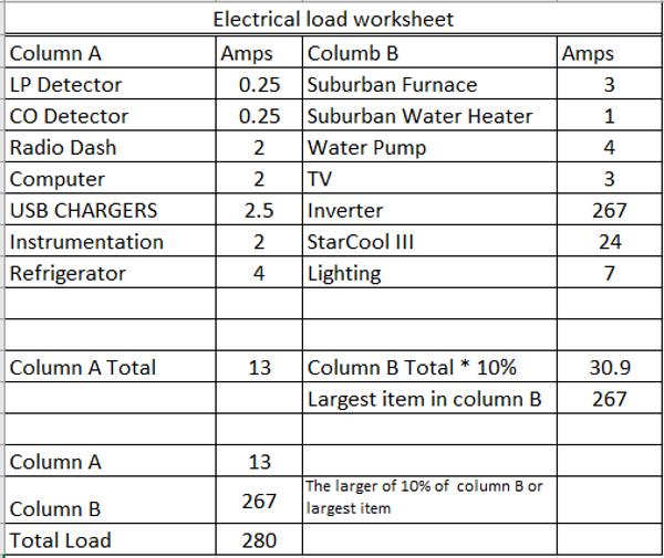
Now unless you like have multiple attachments direct to your battery, you going to have to have a main bus. And if your installing a battery monitor shunt, you need to have a main ground bus. Those of us that have a large inverter/charger are already close. If we fill out the worksheet below, we can come up with a pretty estimate of our worse case load. Column A should be devices that you always have on. It doesnt have to mean 24/7 only but add things that might be on while driving or in a normal camping setup. In column B move things that our intermittent, used as needed. In column B we add up the totals and take 10%, or the highest single load. In my case the inverter/charger load of 267 is still much higher than 10% of the total of B. Adding column A of 13A we get 280-amps.
If we look back at the recommendation of the inverter, we came up with #2/0 and a 300-amp fuse. The 280 still within my ampacity of the #2/0 (330) The fuse 280*1.25% puts us a 350-amps. This is getting closer to a move to the next size decision.
Before we make that decision, we never really discussed voltage drop, the thing that pushes us to a bigger size wire is almost always voltage drop. Because of voltage drop, I went from #2/0 on my inverter to #4/0 wire. In this way I get better voltage drop numbers and provide more ampacity.
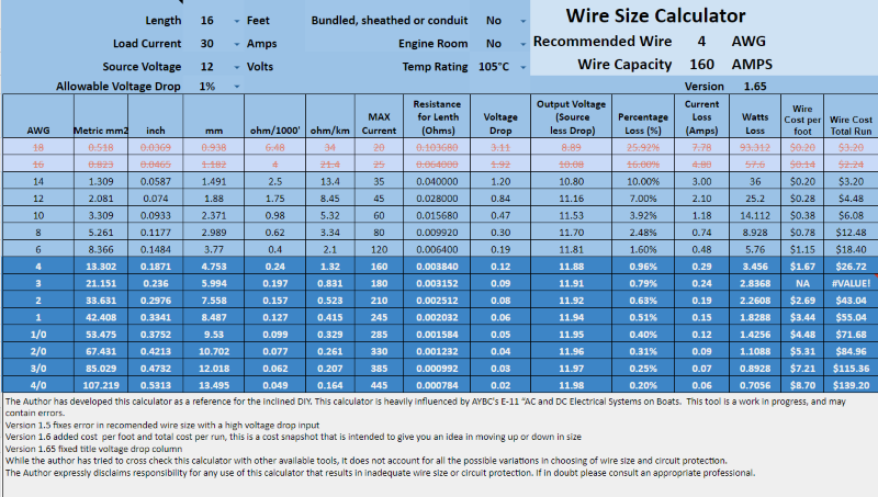
The smaller the size wire, the higher the resistance in the circuit, the more copper we have the lower the resistance. With high voltage drop you not only loose power in getting it to your load, but the load will use more current at the lower voltage. I think this is a case where a nice spreadsheet helps, so I wrote my own Wire Size Calculator. Here we see a 30-amp load 16ft (total run). The smallest wire to do the job is 14-awg, it comes in with a 10% voltage drop. I had put 1% drop into the calculator, and it picked 4-awg, which has a 0.96% voltage drop. With 14-awg we lose 1.2V to drop, while with 4-awg it is 0.12V. A good general rule is to use 3% for your calculations, I have tried to add some cost analysis also to help in making that choice.
Generally, products that have pigtails for attachments, are going to limit the size you may increase due to voltage drop, just be careful on choosing your max wire current, it really should be based on the awg of the pigtail.
Circuit Wizards & wire Size Calculators
One of the most referenced calculators is the circuit wizard by Blue Sea
Circuit Wizard - Blue Sea Systems
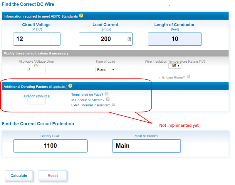
The Circuit Wizard has three major inputs; Circuit Voltage, Load Current, and Length of Conductor (both positive and return). You can also modify the default values; Voltage Drop, Type of load, Wire insulation temp, and engine room. Use variable for a motor or load that might have a larger start up current.
The additional derating factors are not yet implemented. And if you want a fuse recommendation; Battery CCA and Main or Branch Fuse.
The calculator will come up with a recommended wire size, and if you fuse info, it will give you a recommended fuse size
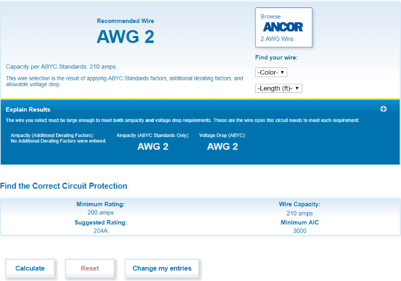
More importantly, since they are in the business to sell fuses, they will give you a chart of their available fuses that meet your requirements.
Another thing to remember is a torque wrench, all these wire connections need to be adequately torque down.
hope all this is useful.
-greg


 Linear Mode