For the most of us, an unfortunate reality is no matter how hard we try, the Sportsmobile spends a large amount of it time in the driveway. A while back there was a good thread going on about plugging in all the time, charging with solar and such. That got me thinking on a way to monitor functions on the Sportsmobile While it sits in the driveway. This program was the result of that.
First a disclaimer, I have no association with any of the products used in this project. I chose them because they filled the solution I was looking for. A couple of the key goals were, being able to monitor the voltage of both house and van batteries, possibly current was from the possible charge sources. I wanted to be able to monitor the status of certain things, Batteries connected, locked and such. I also felt that it would be valuable to be able turn things on or off with this program. My favorite is the Web Cam, but the best part of this is I run this program on my house computer, the attachment to the sensors is done over my home wireless network.

I currently have 8 analog sensors available. I am using:
- Voltage - both house and van
Current - from inverter/charger, alternator, and one left for future Solar install
Water Tank Level
Digital Input
- Separator Status (On/Off)
Pop Top (Latched/Unlatched)
Utility Access Door (Open/Close)
Spare Tire Carrier (Latched/Unlatched) TBI
Water Pump (On/Off)
Radio Switch (House/Van)
Locked Status (Locked/Unlocked)
Run (OFF/ON)
Digital Output
- Separator Disconnect
Radio Switch
Lock/Unlock
Water Pump
Interior Light
Inverter/Charger TBI
Temperature
- Outside
Inside
Refrigerator
Inverter/Charger Exhaust
I already have a computer in the van for infotainment, but the current draw of it is 4.5 t0 6 amps. I really did not want to leave it running 24/7. I had already used a 4-port PhidgetTemperatureSensor from
http://www.phidgets,com I liked there large software library and extensive sample code, they also had an I/O board that had what I was looking for. Then I looked at their 1072 SBC2 board. A Phidget 1072 is a fully functional single board computer with an integrated PhidgetInterfaceKit 8/8/8. At its most basic, it can be thought of as a Phidget that you connect via Ethernet or Wi-Fi instead of directly to the USB. The SBC2 comes with Debian, runs at 400MHz, has 512MB of Flash Memory, and has a battery backed up Real Time Clock. The PhidgetSBC also provides six USB full-speed ports that allow you to use normal USB Phidgets over its network connection. This can extend the effective range of a Phidget from USBs maximum of 15 feet, to anywhere that your network reaches. The great thing about this solution is that even with the USB wireless solution my power draw is only 3.7 watts.

The interfaceKit or "ifKit" has 8 analog input, Sensors that hook up to it must have a voltage output between 0 - 5 volts. This is then broken into a raw value of 0-1000. The easiest thing to do is stay with phidgets as they have a wide variety of available sensors. I used two Phidget 1135 voltage sensors to measure the voltage.


I attached the positive side of each sensor two the Separator Battery connection. This not only keeps my sensor run pretty short, but for debug purposes I really want to know the voltage at the Separator.

The next sensors to be used were for current. Unfortunately the phidget DC current sensors were only 30 amp rated, and the terminal blocks would only hold 10 AWG wire. So I found some hall effect sensors from amploc
http://www.amploc.comthat are rated for 100 Amps and best yet, would fit over the wire from the inverter to battery, I also placed one on the Van side of the separator, this allows me to measure current coming from the alternator or current going to the van battery. I have an extra sensor waiting for a solar install.

Installed: coming from the inverter.

So with other sensor you need to come up with a formula to input the phidget ifKit board. It is not as easy as using one of theirs, but can be done with the documentation provide. Unfortunately the 100 amp sensors are not quite as accurate at low amp draws as I would like.
The last analog sensor was for the water tank level. I purchase a external mount non contact sensor from
http://www.ferriellosales.com/ This was easily adapted to the Phidget Analog input. At first I used 12 volts on the supply side of the sensor; this gave me a very wide raw value range for the water tank level. The problem with using the 12 volts from the battery is that the raw value changes with voltage level of the battery. If I really needed to have more range I would have to go to a regulated 12 volt output, instead I just wired directly to the phidget board and used the regulated 5 volts. An empty tank gives me a reading of zero, when I filled the tank up I then store off the high raw sensor value. Knowing the size of the tank I then can calculate out the level at any time.

Note: For my carputer plug-in, I usually read this sensor when I start the program, and then turn it off, you can imagine a partially full tank sloshes around a lot. This causes the sensor readings to be very crazy. Pressing the water tank label actually forces an update to the reading if needed.
Temperature
I used a phidget 1048 - PhidgetTemperatureSensor 4-Input board. This hooks to the 1072 board through the USB port. I then run thermocouples to the appropriate locations that I want to monitor. I have chosen the outside, inside, refrigerator, and exhaust of inverter. I do have logging built in, so you can log all of the values in 1,10,or 60 second increments. This can be a neat feature to watch the temperature controlled output of your charging source.
I still have 3 positions left; I have been thinking to add a motion sensor that will automatically turn on the web cam and record as a future update.
Now we move to the digital inputs. In the case of the Phidget board an active input would be logic low. All the inputs will go high if not being driven from an external source. One of the first things I wanted know the status of was the separator. In my case I am still using the SurePower 1315. To provide an indicator i used an existing circuit I made for an LED indicator.
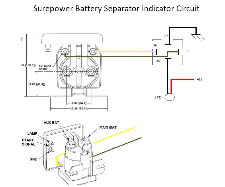
In the case of the ifKit board the ground wire goes to the digital input instead of the ground side of the LED. Although the current draw of the relay is very low, you should always try to limit when they will be active.
The next thing that I wanted to monitor was the water pump. I have had times when parked on a slight angle and with temperature that the pump might cycle on itself if left on. Of course when this happens the pump is very hot. So I pretty much use the same technique, power to the pump drives a ground via a relay. The following shot shows off the relay to the right, there is also another device that I used for the digital input side of things that I will explain later.

The next input I wanted to know the status of was the radio switch; this switch is a little more important for my setup. The wire going to radio is the one that I monitor to power up and turn on my carputer, so if I left it to house side, the carputer would not turn off. Again the same principle, a ground is sent to the phidget input,
I figured if the van was locked or unlocked would be a good thing to know. This unfortunately can be a little tougher to figure out then you would think. Essentially there is a ground pulse for lock on wire and a ground pulse for unlock on another wire. So I really needed top latch the output on lock and unlatch on open. I built the following circuit with relays.

Basically the first two relays on the top are to latch the lock pulse. The relay below that will disconnect 12 volts to the two relays used for the latch thus breaking the latched output. I added the forth relay to isolate 12 volts from the input to the phidget board.

The appropriate wires to hook to were found on the drivers side kick panel.

Note: this circuit works good when using the everything but the key fob, it appears when using the key fob the pulse may be two short for the circuit to work.
The run Indicator I really haven't hooked up yet. But it would be the same idea. The run indicator really came into mind when I was thinking about the next three indicators. These were primarily designed to be used by the carputer software.
The Pop Top Latch.
Have you ever driven off with the latches undone, check out the following circuit I made to detect if the latches were connected?

The premise of this circuit is to provide a ground connection from the frame of the van through the J-Hooks and finally to the phidget ifKit input. I started in the back, The J-Hook connection plate is actually grounded to the frame. Now I attach a wire to the J-hook, using adhesive shrink tube. I carefully ran the wire to the back corner and down the wire loom and then up to the front of the van. Now I need to isolate the J-hook plates from ground, to do this I drilled out the existing whole slightly and the used some isolators that I had made up using plastic washers and spacers.

One for the top

And one for the bottom

I attached them as normal only this time I tied the wire from the back J-hook to one on the front.

Of course the two front J-hooks were tied together with a wire again using adhesive heat shrink. Of course you need to make sure that there is a little bit a heat shrink notched away in the J-hook to provide area for continuity between the hook and the plate. Of course the last J-hook plate is wired to the phidget ifKit input. So when all of the j-hooks are latched the ground from the back connects all the way to the input.

The utility access door.
This was really the easiest to do; I just used a hood pin switch. Door Open it is grounded, door closed it is open.

The last one on the list has yet to be implemented, but I am looking to provide some way to detect if the Aluminus spare tire carrier is latched. Currently I am looking at a magnetic latch but have not had time to install yet.
Now we are to the output section. The phidget ifKit board will provide a High 5-Volt output when it turns something on. Luckily they have two relays that you can hook to the phidget output so you can control the 12 volt stuff in the car. I basically divided the eight outputs in to two Phidget boards, 3051 dual relay boards, and two Phidget 3053 dual ssr relay boards. . The 3051 boards have standard SPDT relays onboard, so you have both a NO and NC side. The 3053 is FET controlled and is like having SPST switch. The input goes to the output when turned on, off it is open. In either case these relays are activated by getting the appropriate 5 volts output from the ifKit Digital output.
3051 dual relay boards

3053 dual ssr board

Separator Disconnect Using a 3051 board I ran the ground for the Surepower 1315 through the NC side of the relay. To disable the Separator the relay is picked by the digital output. In this case I have nothing connected to the NO side of the relay so when engaged it essentially removes the ground from the separator. With it wired this way it will work normally without any power or even if the 1072 is disconnected.
Inverter Disconnect At this time I do not have a solution to turn off the inverter charger. I could use the remote input to change from charge only to invert. But since I only turn the inverter on when I plan on using a device that uses AC this is not something I really need to do. The switch on the triplite to turn the unit off is pretty embedded on the main circuit board; I dont think I want to hack into it. I may end up controlling the AC coming into the unit.
Van/House Radio Switch- I chose to have the ability to control this switch pro-grammatically mainly because I can now turn on the computer by turning the switch to the house position. So if I am getting ready to take the SMB somewhere and want the Carputer powered up before starting, I just activate the switch. Implementing this became more of a challenge, as I still wanted to have the normal switch, I found the solution by purchasing some DEI 611Ts. The 611T is a very useful mosfet controlled switch. You can program it to be NO or NC, it can be switched on using a positive or negative pulse, plus it can be programmed to act as a latch or a timer. In my case I programmed it to be a NO, negative pulse controlled Latch. So to do my radio switch, first I changed the SPDT switch to a SPDT relay. To provide power to relay I chose to use the 12 Volt line from the house battery as the power side of the coil. The ground input of the coil was run through the 611T. To turn on the 611T I replaced the SPDT switch with a SPST (Momentary Switch) to ground, this provides the negative pulse to latch the 611T. In this case it provides the ground side to activate the relay and latch the output. Another pulse of the switch and the output is removed. The nice thing about having negative pulse to activate the switch is that you can easily have multiple turn on switches. You want the Van/House Radio Switch in the back it works, attach another wire to the input from the front (running one wire) and you can add a second switch, and a more if you needed them. In my case, the second switch is the digital out line. For the grounding pulse I chose to use the 3053 relay board. A plus of wiring the 611T as ground for the SPDT relay was that I used that some ground line as the low for my indicator, thus saving an additional relay.

The 611T

So this allows me to have a button controlled by the software, one in the back where the original radio switch was, and also one up front close to the driver. Note: the switches were changed to momentary switches, providing a ground pulse when used.
Water Pump Switch
Again I chose to use a 611T as the water pump switch, this time I did use the switch on the hot side of the pump, the previous switch was changed to momentary switch and a ground wire was run to the 611T. Again the 611t input is also tied to the digital-out line to enable it to be turned on or off via a program.
The 611T is on the left of
Lock/unlock switch - I could have dedicated two switches for this operation, one for lock and one for unlock. As a 1 second pulse on the correct actuator would lock or unlock it. To do it in on switch I again turned to DEI and found a 452T door lock pulse generator. Latch a high and you lock the door latch a low and you unlock the door. Of course you need to tap into the lock circuit, but this was already done for the Relay indicator.
the DEI 452T

The porch light Switch and interior light switch have not been done yet, but I will use the 611T to replace the switch and of use a momentary switch to activate the 611T, or of course the Phidget board.
I am also tying a 611T to the access door switch, this time I am going to use the timer. So when I open the door I will turn on a utility light, it will the go off by itself after a set time.
List of material.
1072 - PhidgetSBC2 -$230.00
http://www.phidgets.com/products.php...roduct_id=1072
1048 - PhidgetTemperatureSensor 4-Input -$100.00
http://www.phidgets.com/products.php...roduct_id=1048
1135 - Precision Voltage Sensor -$19.60
http://www.phidgets.com/products.php...roduct_id=1135
3051 - Dual Relay Board -$19.60
http://www.phidgets.com/products.php...roduct_id=3051
3053 - Dual SSR Relay Board -$30.90
http://www.phidgets.com/products.php...roduct_id=3053
Amploc Key100 Current Sensor -$25.00
http://www.amploc.com/
DEI 611T
http://www.deiproducts.com/servlet/t...iswitch/Detail
DEI 452T
http://www.deiproducts.com/servlet/t...or-Lock/Detail
7400010 - SPST (On)-Off Appliance Rocker Del City
http://www.delcity.net/store/Non!ill...788670.a_1.t_1
This program is really a the standalone version the plug-in I wrote for my carputer sofware.
http://www.sportsmobileforum.com/vie...t=758&start=15
I am
not trying to sell this software, but if anyone wanted to go down this path, I would make it available to them for their own use. I am currently trying to clean it up to make it more configurable, and adding alarm limits with text paging. It was a fun project to do, but I also believe it will be useful in the long run.
-greg


 The big draw to my cameras was they were just in a box and worked, no brain trauma figuring out the system.


 Sportsmobile (AKA Money Pit)
 Any chance you'd tell us what your day job is?

 Linear Mode