|
|
 06-07-2017, 12:16 AM
|
#11
|
|
Senior Member
Join Date: Sep 2016
Location: Denver, CO
Posts: 224
|
I'd say that's CCA, copper clad aluminum. (Somebody else please chime in if I'm wrong....)
4 AWG CCA is perfectly fine to run from the vehicle battery-solenoid-house batteries, charge line.
4 AWG CCA is perfectly fine for all your grounding needs with a 1500watt modified wave inverter. (Pure sine inverters I would use equal size OFC for grounding also)
IMO, use 4 AWG OFC between the house batteries and the inverter. That is where the amps will be drawn. Amps = heat. You can usually get OFC on ebay for around $1.50 a foot.
Electrical is pretty easy. You should do it yourself. If you go to an RV/Van shop, they are going to charge you 10x the price and probably build you something you don't need. Solar systems are great also, I run one on my son's race trailer and it has been maintenance free for over a year. Simple and reliable. I've done a video on what I run in my van. If you want I can do a more in depth video and post it.
There are many opinions out there and none are wrong. It boils down to basic things, what do you need, what will be safe, what will be reliable and what will be cost effective. My dual house battery system cost around $500. Took about two days of working on it in the evenings after work to build it. Got my 34 series AGM batteries at Sams Club, VSR and inverter from Amazon, wire from ebay, fuses I got from my friend who does auto/diesel electrical work. Used a $16 hammer crimper. (Don't waste your money on the Harbor Freight hydraulic crimper, dies are sharp and will cut your terminals). The one thing I will do in the future is spend the cash for a pure sine wave inverter that way I can run my laptop and tv from the inverter. I can only charge HD electronics with the modified wave.
Also IMO... I would ditch the idea of using an external hook up. If you have a solenoid to charge and solar, that will be plenty to keep your power up. I only use a VSR to charge and it only charges when the vehicle is running. I've sat for up to 14+hrs running my cooler and then my electric blanket and haven't dropped the charge under 11.6v (20%) on the dual batteries.
Having a solenoid charge while you're driving and solar while you are parked will probably keep your batteries fine in 90% of your usage. Again, IMO. How many places will have power hook ups where you're camping? Solar will maintain the batteries while it is parked in your driveway. I've let my system sit for over a week without starting my van to charge the house batteries and they haven't dropped below 12.5v. As the batteries age they will drop more, but they have a 36 month warranty, so its not that big of concern. (I have my batteries wire in parallel, not series.)
__________________
2010 Ford E350 EB 6" Weldtec Lift
2017 Subaru Legacy
1990 Volvo 240GL
2x 1987 BMW 535is
1995 BMW 540i6
|

|

|
|
06-07-2017, 05:09 PM
|
#12
|
|
Senior Member
Join Date: Apr 2014
Location: Terrebonne, Canada
Posts: 218
|
Quote:
Originally Posted by winmag4582001

I'd say that's CCA, copper clad aluminum. (Somebody else please chime in if I'm wrong....)
4 AWG CCA is perfectly fine to run from the vehicle battery-solenoid-house batteries, charge line.
4 AWG CCA is perfectly fine for all your grounding needs with a 1500watt modified wave inverter. (Pure sine inverters I would use equal size OFC for grounding also)
IMO, use 4 AWG OFC between the house batteries and the inverter. That is where the amps will be drawn. Amps = heat. You can usually get OFC on ebay for around $1.50 a foot.
|
Ok cool, I only have 3 feet between the inverter and the battery, I'll use OFC for that part and keep the ACC for the rest.
Is there any other place I would need OFC? Between the batteries and the charger/converter/dc panel?
Quote:
Originally Posted by winmag4582001
Electrical is pretty easy. You should do it yourself. If you go to an RV/Van shop, they are going to charge you 10x the price and probably build you something you don't need. Solar systems are great also, I run one on my son's race trailer and it has been maintenance free for over a year. Simple and reliable. I've done a video on what I run in my van. If you want I can do a more in depth video and post it.
|
At first glance do you see anything wrong with my drawing? the "electrical setup" that I posted in the first message.
Quote:
Originally Posted by winmag4582001
There are many opinions out there and none are wrong. It boils down to basic things, what do you need, what will be safe, what will be reliable and what will be cost effective. My dual house battery system cost around $500. Took about two days of working on it in the evenings after work to build it. Got my 34 series AGM batteries at Sams Club, VSR and inverter from Amazon, wire from ebay, fuses I got from my friend who does auto/diesel electrical work. Used a $16 hammer crimper. (Don't waste your money on the Harbor Freight hydraulic crimper, dies are sharp and will cut your terminals). The one thing I will do in the future is spend the cash for a pure sine wave inverter that way I can run my laptop and tv from the inverter. I can only charge HD electronics with the modified wave.
|
I did order a hammer crimper on amazon 
Quote:
Originally Posted by winmag4582001
Also IMO... I would ditch the idea of using an external hook up. If you have a solenoid to charge and solar, that will be plenty to keep your power up. I only use a VSR to charge and it only charges when the vehicle is running. I've sat for up to 14+hrs running my cooler and then my electric blanket and haven't dropped the charge under 11.6v (20%) on the dual batteries.
Having a solenoid charge while you're driving and solar while you are parked will probably keep your batteries fine in 90% of your usage. Again, IMO. How many places will have power hook ups where you're camping? Solar will maintain the batteries while it is parked in your driveway. I've let my system sit for over a week without starting my van to charge the house batteries and they haven't dropped below 12.5v. As the batteries age they will drop more, but they have a 36 month warranty, so its not that big of concern. (I have my batteries wire in parallel, not series.)
|
Too late the 30amp inlet is already installed on the outside wall and I also bought the transfer switch.
__________________
DIY conversion build, extended 2010 Ford 5.4L E250 + high top, from Montreal Canada, new to all this so please be patient and clear with me (never built or camped in a van yet)
|
|
|
|
|
06-07-2017, 06:02 PM
|
#13
|
|
Senior Member
Join Date: Apr 2014
Location: Terrebonne, Canada
Posts: 218
|
Quote:
Originally Posted by winmag4582001
The one thing I will do in the future is spend the cash for a pure sine wave inverter that way I can run my laptop and tv from the inverter. I can only charge HD electronics with the modified wave.
|
I bought a Whistler 1600watt inverter on amazon, it's very well rated, yes it's a modified sine wave inverter but I red the reviews and a lot of people who bought it use it to run laptops... What are the risks?
__________________
DIY conversion build, extended 2010 Ford 5.4L E250 + high top, from Montreal Canada, new to all this so please be patient and clear with me (never built or camped in a van yet)
|
|
|
|
|
06-07-2017, 06:53 PM
|
#14
|
|
Senior Member
Join Date: Sep 2016
Location: Denver, CO
Posts: 224
|
Quote:
Originally Posted by evy
I bought a Whistler 1600watt inverter on amazon, it's very well rated, yes it's a modified sine wave inverter but I red the reviews and a lot of people who bought it use it to run laptops... What are the risks?
|
Many times the modified wave will distort the screen on HD laptops, ect. Modified also can be hard on electronics like an electric blanket with a digital controller or digital display coffee makers.
Myself, in the future I'm going to spend the extra cash on a pure wave so that I can grab any device from the house and plug it into the van.
__________________
2010 Ford E350 EB 6" Weldtec Lift
2017 Subaru Legacy
1990 Volvo 240GL
2x 1987 BMW 535is
1995 BMW 540i6
|
|
|
|
|
06-07-2017, 06:57 PM
|
#15
|
|
Senior Member
Join Date: Sep 2016
Location: Denver, CO
Posts: 224
|
You're drawing looks fine. If you are worried about anything, just use fuses that are lower blow.
I have a 100amp between my vehicle battery and VSR. 50amp on both the inbound charge lines to the house batteries. 150amp between the house batteries and inverter. 60amp running to my DC fuse panel.
__________________
2010 Ford E350 EB 6" Weldtec Lift
2017 Subaru Legacy
1990 Volvo 240GL
2x 1987 BMW 535is
1995 BMW 540i6
|
|
|
|
|
06-09-2017, 08:29 AM
|
#16
|
|
Senior Member
Join Date: May 2007
Location: Beaverton, OR
Posts: 2,504
|
I guess I would take a different approach, to this. I in no way use Copper Clad Aluminum wire. For the wire in question the ampacity of the CCA wire would be the same as using 6 gauge copper wire. While you could adequately account for that. I would say that mixing could get confusing at a later date, and more importantly to someone else down the line.
As for the term OFC or Oxygen Free Copper, while there are purposes OFC, power and battery cables is not one of them. Standard Copper Wire has 99.5% copper while Oxygen OFC is 99.55%, this of course comes at a higher cost to produce. We could spend a whole thread on wire, but it would be reasonable to say the wire appropriate for battery and power wires in our vans would be: Marine, SGT, and SGX. Many people use welding wire also, but there can be some concern over the properties of the insulation when used in some locations such as engine compartments.
As important as the actual material used in the wire, the insulation material is equally used. The temp rating should be identified on the insulation and it is important when we calculate out if the capacity of the circuit. So it is just as important to identify the wire size, type and insulation. The third and sometimes most important item is voltage drop, or how much do we want to allow for the voltage drop of the circuit.

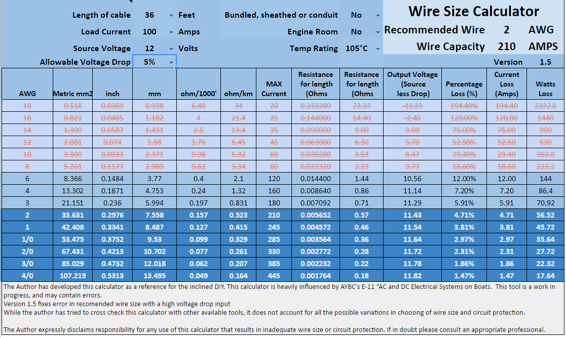
Looking at your diagram, we should first try to identify the device that is going to be the largest power draw and start there. I think that was correctly identified as Inverter, which I believe is listed as 1600 watt inverter. To adequately come up with the wire size, we need to identify the path both to and from the battery. In your diagram, I have identified the positive path in red from Inverter to bus bar, and yellow from bus bar to battery. I also identified the ground path the battery in green and dark blue. You have listed the length from the inverter to the bus bars as 3 ft. each the positive path from the battery to the bus bars is not listed, but for the purpose of calculations I will include an additional 4 ft. So for a total length of the circuit we will use 10 ft. as our distance.
The next thing we need to identify the load, so again you have listed a 1600 watt inverter, but we cant use 1600 watts as our maximum load because of the power conversion of the inverter itself, the manual does not specify the conversion cost, so I will use an assumption 20% for calculation. So we have a load 1920 watts. The next derating factor is based on worst case voltage. We need to account for voltage in our load calculations. Looking at the manual I believe a low voltage lock out occurs at 10.00 volts (at the inverter), so we will use 10 volts in our load calculations giving us 1920 / 10 or 192 Amps. This becomes are worse case load value as opposed to 1600/12 or 133 amps. Using the Bluesea calculator 192 amp load 12 volts 10 ft. circuit length with wire that is 105 °C temp rating gives us a recommended wire size of 1 AWG. This is on the edge of a 2% voltage drop and adding another foot to the calculation puts you a 1/0 AWG.
My calculator below shows 1/0 AWG as the recommended wire size.

Your manual recommends 4 AWG
For XP1200i and XP1600i When the inverter and the battery are set up within three feet of each other, use a minimum of #4 gauge wire to make the connections. Within four to six feet, use a minimum of #2 gauge wire for XP1200i, #0 gauge for XP1600i. At distances between six feet to ten feet, use #0 gauge wire for XP1200i, #00 gauge for XP1600i.
I would assert that is correct for the 1200i but the 1600i would need to be 2 AWG, as they identify a different gauge for all their other examples. And the numbers dont get me to 4 AWG. Also the manual does not express either a rated temperature or voltage drop used for the equation.
It should be clear that the wires from the bus bars to the battery at a minimum must meet the load of the highest source. It could also be argued that those wires must cover at a minimum of the max load of the inverter and whatever other load could be on the battery at one time (any always on circuits, devices that could cycle on while using the inverter, or anything that most surely could be used while using the inverter) It would be very easy to convince myself to move to 2/0 AWG G to cover any possible updates to the setup.
Also, importantly your bus bars also need meet the same ampacity requirements of the cable they are connected to, as they are an integrated part of the circuit. The purple wire that connects the positive to negative of your two six volt batteries should also meet the highest current requirements.
Item #C3 is listed as a main kill switch, this really should be where your main battery fuse placement should be. It should account for the current requirements and have at a minimum 5000 AIC current specs.
If you use larger wires from the battery to the bus bars than from the bus bars to the inverter than you most likely need a smaller fuse to protect that downsized wire. You show a fuse/breaker on the input of the inverter, this would be more appropriately located closer to the bus bar as its purpose is to protect the wire.
For your alternator to house battery circuit, you list 18 ft. so I will use 36 ft. in the calculator for the total circuit. In reality you wont be running a ground wire back to the starting battery as you will have both grounded to the frame. I will use 100 amps for the load, the driving force will be voltage drop. I use 5% and get 2 AWG 105°C rated wire. I will note that 6 AWG 105°C has the Ampacity to cover the 100 amp load, but has a large voltage drop.
I have to disagree with Winmag on that over a 50 amp load being a problem, I have data that shows 75 to 80 amps with a alternator in that range.
You can find a copy of my wire calculator at https://docs.google.com/spreadsheets...it?usp=sharing
-greg
__________________
-greg
__________________________________________________ ______________
"Goldilocks" 2020 Ford Transit High Roof Extended 3.5 EcoBoost AWD Homebuilt
|
|
|
|
|
06-09-2017, 06:03 PM
|
#17
|
|
Senior Member
Join Date: Apr 2014
Location: Terrebonne, Canada
Posts: 218
|
Thanks again Greg!
I did all the modifications to my diagram today.
I will be posting them here soon.
I wanted your opinion on the alternator hookup, you corrected my drawing, connecting the relay directly to the battery instead of the alternator.
In my earlier version of the drawing it was connected that way but someone told me this :
the "existing wire" (between the vehicle's battery and the alternator) was never designed to pass the additional current required when a depleted set of golf cart batteries is added onto the end of the circuit. it becomes an electrical bottle neck, and might blow the "existing wire's" fuse. This alternator load dump might fry the diodes in the alternator.
IF you INSTEAD, take power for relay not from engine battery, but from alternator(+) stud, you eliminate the too thin "existing wire" from limiting house battery amperage, AND you also likely have a shorter circuit, AND one which does not require a Fuse as you only need to fuse close to the battery, either battery.
Would you agree?
__________________
DIY conversion build, extended 2010 Ford 5.4L E250 + high top, from Montreal Canada, new to all this so please be patient and clear with me (never built or camped in a van yet)
|
|
|
|
|
06-09-2017, 10:06 PM
|
#18
|
|
Senior Member
Join Date: May 2007
Location: Beaverton, OR
Posts: 2,504
|
In general we try not deplete our battery system below 50%, but it certainly would be possible that your battery system was depleted lower, in that case the load on your alternator would be the same in either location. This is one of the reasons that the voltage sensing relays are a plus, because in theory they would not close until the alternator charged the van battery, enough for the voltage to go up, and thus close the relay. This would at least limit the load caused by the starting battery
The existing wire should be sized for the existing alternator which is your power source. If you have a larger aftermarket alternator installed I would certainly say that the wire needs to changed to account for that.
You would still need to fuse the wire in my opinion, and it is generally easier access to that fuse at the battery instead of at the alternator.
-greg
__________________
-greg
__________________________________________________ ______________
"Goldilocks" 2020 Ford Transit High Roof Extended 3.5 EcoBoost AWD Homebuilt
|
|
|
|
|
06-10-2017, 02:44 PM
|
#19
|
|
Senior Member
Join Date: Apr 2014
Location: Terrebonne, Canada
Posts: 218
|
Here's the new drawings up to date (with added solar power).
Also I added a new drawing of the main kill switch/positive bus bar (to scale) don't hesitate to let me know if you see anything wrong or if you have any advice. I will be doing the bus bar myself with a 1/4" thick aluminum flat bar.
The cable length for the inverter will really be 2 x 3ft, so I used the blue sea circuit wizard and I get 2awg (instead of 4awg from the inverter's manual as mentioned by Greg)
I'll try to get my hands on some good 2 awg copper wiring and lug/terminal.
I was shopping for log/terminals and I noticed that there are two kinds (copper and tinned copper) do I have to stay away from them as well?


__________________
DIY conversion build, extended 2010 Ford 5.4L E250 + high top, from Montreal Canada, new to all this so please be patient and clear with me (never built or camped in a van yet)
|
|
|
|
|
06-13-2017, 10:20 AM
|
#20
|
|
Senior Member
Join Date: Apr 2014
Location: Terrebonne, Canada
Posts: 218
|
Quote:
Originally Posted by Scalf77
...with wire that is 105 °C temp rating...
-greg
|
Quote:
Originally Posted by Scalf77
Many people use welding wire also, but there can be some concern over the properties of the insulation when used in some locations such as engine compartments
-greg
|
I'm currently shopping for 2awg wiring, first place I look is craigslist, then I look to buy it new.
And you're right, many people use welding wiring, I even shopped online for brand new big gauge battery wiring and when you look at close up pictures of the cable it's written "welding wire" on it...
But if I understand, if the temps rating is 105°C it will do the job (even in the engine compartment?)
What is the risk of buying used welding wiring?
I'm thinking the outside can be used up from rubbing on the ground and may be damaged from objects in the shop?
__________________
DIY conversion build, extended 2010 Ford 5.4L E250 + high top, from Montreal Canada, new to all this so please be patient and clear with me (never built or camped in a van yet)
|
|
|
|
|
|
 Posting Rules
|
You may not post new threads
You may not post replies
You may not post attachments
You may not edit your posts
HTML code is Off
|
|
|
|
 » Recent Threads
 |
|
|
|
|
|
|
|
|
|
|
|
|
|
|
|
|
|
|
|
|
|
|
|
|
|
|
|
|
|
|
|
|
|


 Linear Mode