This mod can really be broken into two parts, but both were performed at the same time. Either one of these modifications could be a standalone mod. The first modification was a redundancy switch for the Battery Separator. I have the SurePower- 1315,

some of the details of this are exclusively for the SurePower units but, the overall concept will work with any Separator. In fact, if I had not already just purchased a replacement 1315 a couple of months ago, I would have probably purchased the Blue Sea 7620 or 7622.

With my redundant mod I would recommend the Blue Sea 7620 as the manual control would be well redundant. The concept of the redundant switch is to put a wire in parallel to the separator. You then can choose to use the separator path or the straight wire. For this I chose the Blue Sea m-series 6007 Selector Battery Switch.

. This switch has four positions, off, 1, 2, and 1&2 combined. I moved the 2ga wire coming from the House Battery to the Battery Separator to the input of the Battery Selector Switch. I then added a cable from output 1 of the switch to go to the House battery side of the Battery Separator, this was followed by a cable from output 2 of the battery switch to the Van side of Battery Separator. Now I have a redundant system.
Switch Off House Battery Isolated from the Van Battery completely independent. This is a plus when you take it in for any work on the van side of things.
Switch (1) I would call this my normal position, it will just put the Battery Separator back in the circuit and will be just like the factory install.
Switch (2) is really my redundant feature, if you are having problems with the separator , this will just bypass it and connect the two battery systems.
Switch (1 And 2 combined) This just engages both one and two, no real big use here, although I believe I read in a previous thread about shorting the terminals on the SurePower make it work again? But I have no personal experience with that.
 Stock Sportsmobile Wiring
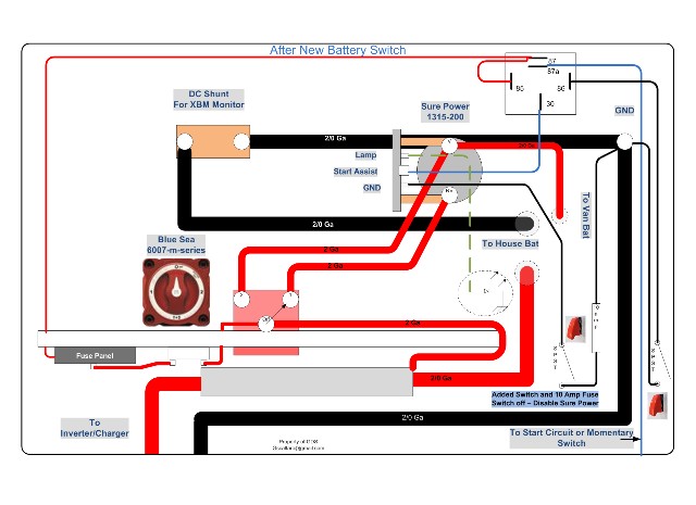 After Redundant Switch installed
So like I said I could have chosen the Blue Sea 7622 and it has a manual switch to override the automatic connection feature of the ACR. If I was replacing the SurePower I would probably go with 7620. One of the reasons that I came to this conclusion was because of the failure of my previous SurePower 1315. The failure mode that I had appeared to be resistance build up on the contacts the unit, from all I could tell the unit was connecting at the proper voltages, but I could not supply enough current to charge the batteries while driving (and using the Starcool Air-condition ). So in theory if contact resistance build up was the problem then a manual connection of those contacts would still result in the same problem. It is possible that because my Surepower unit was wired incorrectly (To the run circuit instead of the start circuit) that this helped facilitate the failure. The nice thing about having a separate unit is that if you are having problems it aids in debugging the problem.
While I was here I added a few things to the SurePower factory circuit. First I Added a switch and 10 amp fuse to the ground circuit on the SurePower unit. The latest technical documentation for the Surepower unit has a 10 Amp fused used on the ground side.
http://www.surepower.com/pdf/180074d.pdf. Adding the switch give me away of disconnecting the separator, of course just pulling off the ground wire does the same thing but, I have to take the gaucho cushion off to get to it. The second change I made was to use the Start Assist option to let me turn on the Separator if I wanted to. The simplest thing here would be to just wire in the switch to a hot wire, this would of course disable the automatic start wire done by the factory (Correctly or Incorrectly). I chose to run the start assist wire through a SPDT Relay, with the existing wire, going through the normally connected side. This allows that circuit to work as you already have it. The Normally closed part of the relay will provide the 12 volts to the separator when switched on. For the record I have gone the way as some others and wired the start assist wire to a momentary switch instead of the Start Circuit Now I have a Separator that I can force on or off with a switch , with a redundant backup. For both of these switches I used covers that force them to be in their normal operating position. In either case you have to go out of your way to enable the switch, but you could use a switch of your choice. As I said these are not really needed, although if you were there you might want to look at putting the 10 amp fuse to ground.
The second mod is a low voltage disconnect switch. First this mod requires the use of a Xantrex XBM or similar unit that monitors voltage and has controlled outputs. In the case of XBM it has a controlled relay; you can program the relay outputs to be Normally Open (Default) or Normally Closed. For my application I chose to use the default setting in Normally Open, which means when the low voltage set point is met, it will close the relay. The hart of the disconnect switch is the Intellitec 100 Amp Disconnect Switch.
 http://www.intellitec.com/PDF/5300066.100.pdf
I got the idea looking at the Blue Sea ML-Series Heavy Duty Solenoid Switch (Magnetic Latch) - 7700 or -7701.

This is really just the Blue Sea 7620 or 7622 without the automatic voltage sensing circuitry. I could not justify the cost of $140.00 for one of the Blue Sea Units when I found the Intellitec unit for $53.00. The beauty of the Intellitec unit also is that once it has been engaged or disengaged it no longer draws any power. Intellitec has two input connection to close the S and I, a input and output, they also have two fuse holders for that can be connected to the input and output terminals. To close the relay you need t provide +12 on the I terminal and Gnd on the S terminal to open it you provide Gnd on the I terminal and +12 on S terminal. This is done using a momentary DPDT switch (on) off ( on). By crossing the +12 and Gnd connections you can provide the necessary polarity across I and S to close or open the Solenoid Switch. Because the switch is monetary it will come back to the off position. I picked the 12 volts off of Battery side of Solenoid Switch using the fuse holder supplied. So Now I just have a fancy disconnect switch that I need to get to disengage when the XBM reaches it low voltage set point.

Figure 3 Low Voltage Disconnect Switch
This was done using two SPDT relays, the outputs of the momentary switch were run through the NC (87a) side of the relays, the common output (30) went from the relay to the I or S input of the Intellitec Solenoid Switch. Now I use the 12 volt fuse on the output side of the Solenoid switch to provide 12 volts for the relays (84) . A wire from ground is run to the XBM pin A1 and then a wire is run from XBM A2 to the Gnd (86) input of the relay. The relay going to Terminal S Has 12 volts also going to the NO input (87), while the relay going to Terminal I has GND going to the NO input(87). So when the XBM reaches the low voltage set point it closes the relay which now provides a Gnd to pick the relays to shut off Intellitec Battery Solenoid. The problem with that is that I need to create a pulse, now that I have put the correct polarity to move the magnet to the open position I need power to go away. To create a pulse using a relay I put a 2200uF Capacitor on the ground side of the relay coils. With the two relays in parallel it should take about ½ second to charge the relay, this will effectively create an open and the two relays will disengage removing power and ground from the I and S terminals . As power goes away the solenoid plunger will disengage and remove power from the distribution side of the Battery Switch. There is also 10K resistor in parallel to bleed the cap once power is removed. So now power to the distribution side of switch and the battery should be protected. I wired another Blue Sea 6007 switch in parallel in case I need to bypass the Intellitec Battery Solenoid all together.
 Combined modification Switch
I started the modifications by disconnecting the ground connections on both batteries. The next step was to disconnect the wires going to the separator. I also removed the old distribution panel, as I was replacing the MDF panel with Baltic Birch Plywood. At this time I chose to replace the existing fuse panel with a new Blue Sea panel that has room for expansion. The new panel was wired in the garage, I also made a panel to hold both the Surepower and the new intellitec switch and relays


Now we are ready to go back in the van. There are four wires that need to be hooked up. I have already hooked up the existing Surepower Start Assist wire to the relay three (87a)

The existing cable from the inverter fuse to the separator had a 5/16 lug on it, it also could be shortened a little bit.
 Old Sportsmobile Crimp
 New Crimp with Larger Lug
I used two different ways to make the cables; the best way is with solder. See the link below for a good tutorial
http://www.delcity.net/documents/movies ... minals.mpg. The second method is with an a big cable crimp tool.

I used the solder method for the 2 Gauge cable and crimped connectors on the 6 gauge. Both methods work fine, the above 2 gauge crimp was made with the crimp tool as I was inside the van. I all cases using good heat shrink make for a nice finished cable. Now it is time to reinstall the cables.

I now have covered the cables with split wire loom for protection and reinstalled the starcool relay panel
. The new panel and switches ready to go


Last but not least the two wires were run to A1 and A2 on the Xantrex Battery Monitor and everything was tested out. The low voltage disconnect uses an already existing Xantrex Battery Monitor
Obviously the difficulty of this mod depends on your comfort with electrical work; there was also some minor woodworking for the new panel. See some of the tools used below.
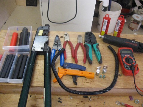
-greg


 The Blue Sea switches are a great find, photos are excellent and even if I don't repeat this actual mod there is so much good info in there I'm going to have to follow BW in re-reading the whole thing.


 Linear Mode