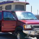
As noted above, my 1998 Ford SMB with Starcool III lacked the remote on/off blower switch that became standard in 2000. It was a pain always having to go back and turn the blower fan on/off when starting out or parking. I coveted the remote switch those of you with the newer SMBs have. I finally got around to doing this mod last week, with many thanks to the schematic that Scalf77 posted of the newer Starcool III with remote switch.
Instead of adding it behind the driver's head, I decided to install a lighted switch on the dash HVAC panel, just under the blower speed switch. This is where the OEM rear AC blower switch would mount on vans so equipped. I figured it would a lot easier to access there, more tightly integrated with the whole "AC experience," and since it's a lighted switch I'll be less likely to forget to turn it off.
Even if you have the SMB-installed remote switch already, you may want to consider moving it to the dash position like I did. It would be a really easy mod, as you have the relay and whatnot already wired by SMB. You'd just have to run some wiring.
Scalf77 did a great write-up about adding a similar switch to the same area, but using a multi-speed control and several relays. It's a great idea, but I didn't want to get that involved. If you feel motivated, you can find his excellent thread here:
viewtopic.php?f=13&t=3260
Here's a write up on what I did.
Tools and stuff you'll need:
1. Wire to reach from the Starcool relay panel to the dash. I used 16 gauge, since it's not carrying much load. Also, shorter pieces for the relay jumpers and dash power and ground wiring.
2. Wire connectors ring or spade connectors, and at least 7 insulated female push connectors (4 for the relay, 3 for the switch).
3. Wire stripper/crimper
4. Screwdrivers
5. Trim removal tool (or big flat screwdriver)
First, add a fifth relay to the Starcool relay panel (probably under your gaucho or dinette seat). See the schematic above for how to run it. Find the fuse for the blower (20 amp fuse) and pull it. Trace the wire from that fuse position to the relay distribution block (location #8 in the schematic). Disconnect the downstream wire (the wire that goes to the blower). Make up a small jumper cable to go from the distribution block to the new relay. It should have a spade or ring terminal on the end that goes into the block and a female push connector (insulated) for the end that goes into the relay.
Heres where my install varies from the SMB schematic above: if you are installing a lighted switch, do NOT jump the two connectors on the relay (87 and 86). Just attach the wire from the distribution block to terminal 87 on the relay.
[If you are installing a NON-lighted switch, like SMB does, set it up like the schematic by jumping a wire from relay terminal 87 to 86. This is most easily done when you are making up the jumper cable from the distribution block -- crimp a second wire into the push connector end at the same time, and then add another push connector at the end of the second wire.]
Next, take the original wire you disconnected from the distribution block, cut off the SMB-installed spade connector and put a female push connector on it, and attach it to relay terminal #30. This is the wire that provides power to the blower. Finally, run a ground wire from relay terminal 86 to a suitable grounding position on the van body/frame/whatever (I found a bolt in the inverter compartment that connected to the frame and just tagged onto that).


 Linear Mode