|
|
 09-28-2016, 06:03 PM
|
#11
|
|
Site Team
Join Date: May 2007
Location: Southern New Mexico
Posts: 10,179
|
Bittersweet when I read a thread where Ramsey has posted. I miss his advice.
Herb
__________________
SMB-less as of 02/04/2012. Our savings account is richer, but our adventures are poorer.
|

|

|
|
09-28-2016, 08:44 PM
|
#12
|
|
Member
Join Date: Oct 2014
Location: TN, Nashville
Posts: 72
|
Dimensions
Indeed, Ramsey was so generous with advice. So non-judgmental when a crowd of amateurs sought out information. As a high school teacher I have tremendous respect for those who pass on their knowledge and are able to explain so many relevant ideas. A great man.
I posted this info originally on someone else's build thread over on expo, but keep having to hunt it down. With a new audience I figured I should consolidate. So if anyone needs dimensional information on dana50 mount points:

The width center to center (E) on the pivots is around 7".

A: ball joint to ball joint: 54 3/8"
B: Pivot overlap: ~5 1/4 inches
C: Leaf centering holes: ~38"
D: WMS to WMS (measured when wheels were welded to square tube, before axle installed between them.)
I plan to use a moogCC880s spring. Before removing my original i-beams, I measured that the weight of my van would compress these springs to a height of 14.5 inches.
|
|
|
|
|
09-29-2016, 09:45 AM
|
#13
|
|
Senior Member
Join Date: Jul 2011
Location: GTA, Ontario
Posts: 1,102
|
Just finished reading about these swaps and now realize you only need two radius arms not a 4 link setup because the axle housing pivots will prevent twisting. Much simpler.
Sent from my iPad using Tapatalk
__________________
"Talk is cheap. Whiskey costs money."
|
|
|
|
|
10-04-2016, 05:45 PM
|
#14
|
|
Member
Join Date: Oct 2014
Location: TN, Nashville
Posts: 72
|
More measures
I started this project when my son was one year old. He is now more than a year older, and as of Saturday is also a big brother.
Improving on my jig, I welded vertical supports connecting the jig and the axle so that the position of each beam won't move while I mock up brackets.

I've hung a pair of bobs down from the center of the spring mount to a distance of 14 1/2". (The height of the CC880S spring compressed by my van's weight.) The axle will be centered front to back under these bobs.
I then found two points along the frame (+ the string from the bob) to use as reference points to be sure the axle was centered right to left.

|
|
|
|
|
10-07-2016, 07:27 PM
|
#15
|
|
Member
Join Date: Oct 2014
Location: TN, Nashville
Posts: 72
|
Opinions on bumpstop height
Opinions:
How much clearance should a van have between ttb beams and bumps?
Reason:
Mine are close. I've mocked up cardboard templates of my perch mounts that look similar to the agile setup. My height is determined by my desire to use the cc880s springs. I have about 1.5" of uptravel before the beams touch the bumps. The bumps are ~22" from the perch and the inner surface wheel edge is ~32". Without really thinking this through, I should get about 150% of those 1.5" in uptravel at the wheel which would be 2.25", plus compression of the bumps.
There are obvious solutions: taller spring mount (and lower pivot brackets), lower rear edge where beam and bump contact, different springs. Some of these options will be better assessed when I built some temporary beam mounts and cycle the suspension.
Some photos:

On the driver's side beam, the stop will need to be moved forward over the driver side beam, since the driver beam and passenger beam have swapped front to back relative to a 2wd setup.

Just a head on shot of one of the two beams.

|
|
|
|
|
10-12-2016, 02:57 PM
|
#16
|
|
Member
Join Date: Oct 2014
Location: TN, Nashville
Posts: 72
|
Cardboard Aided Design Issues
A member over on expo posted a ttb conversion done by clydesdale conversions. I liked the fact that the bracketry was bolt up, as opposed to Agile's which is a welded application. So I set out to replicate elements of those brackets.

Here's my CAD mockup approximately in place. Enough to realize that it won't work. The clydesdale conversion is done using dana 44 beams. Note the much longer diff-side beam on the clydesdale van. After hot gluing this bracket together, then sliding the axle further, and further, and further and further forward, until the bracket was in placeI'm abandoning the bolt-on approach.

The beam has to be slid forward so far that the beams are no longer under the spring perches. Moving the spring perches isn't on the approved to-do list for this project. Here the locating nut is directly under the center of the spring.

Back to the bumpstop clearance issue from my last post where there was 1 1/2" from beam to bump. I had a set of 2" coil spacers sitting around. I really want to just keep the springs simple since I know that IFS on the CC880s springs with stock geometry is a nice ride. Looking back a the first photo in this post, spacers are clearly part of the clydesdale conversion. So I'll try that. Much better. Now nearly 3" of space between beams and bumps. With 150% gain at the wheel, this will mean around ~4.5" of uptravel before the bumps. Other things will probably limit uptravel first... just need to make sure shocks aren't the limiting factor. I have a quote of $500 for a set of custom wound springs later if I like the height results. I'll add two holes at different elevations to the pivot bracket to facilitate either coil spacers with 880s or 880s without spacers.

The spring centering nut sits right in the middle of the spacer.
|
|
|
|
|
10-14-2016, 02:24 PM
|
#17
|
|
Member
Join Date: Oct 2014
Location: TN, Nashville
Posts: 72
|
Ideas falling into place
So here's an issue:

Notice that any upward movement of the differential will send it into the flange on the ECM. I can't move the axle+differential forward to clear the flange, else the spring buckets will no longer sit directly above the beams. Same issue as earlier posts.
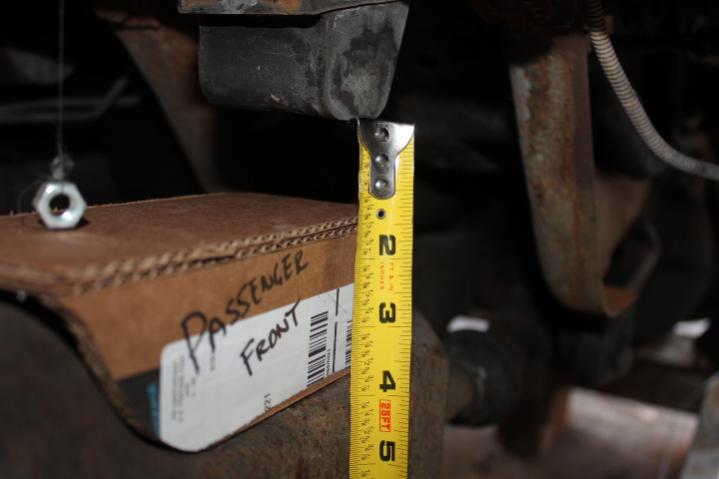
The solution in short is to heavily modify the ECM to eliminate that portion all together and compensate for the structural loss in the bracket. Here's a view of the bracket, from the rear, looking on the top surface that will mount to the underside of the ECM. Notice the one hole drilled... and the two faintly marked to be drilled later.

Those three holes will align with the three holes you see below from where the studs on the factory i-beam pivots used to be located. I'll reuse these holes with bolts in place of the old weld in rivets.

The whole thing will bolt, then weld up something like this. The rusted/cut-off stud that you see at the top of the previous photo is barely visible in this photo.

The ECM will be cut along the left side of the cardboard bracket, and the differential (visible in the bottom of the photo) will have a load of extra clearance, now able to swing in front of the ECM. A new flange will be welded to the cut edge of the ECM and the bracket, extending upwards, replacing the function of the cutaway portion.
|
|
|
|
|
10-14-2016, 09:02 PM
|
#18
|
|
Senior Member
Join Date: Feb 2015
Posts: 175
|
Is there a reason you couldn't offset the coil mount back on the beam to allow it to move forward? You are fabricating the lower coil mounts? These vans usually gain a lot of tire clearance by moving the front axle forward.
|
|
|
|
|
10-15-2016, 11:55 AM
|
#19
|
|
Senior Member
Join Date: Jul 2011
Location: GTA, Ontario
Posts: 1,102
|
Dana 50 ttb conversion log.
How are you placing the beam pivot holes in the bracket to guarantee correct caster? I figure this setup's caster is highly dependent on the placement of the holes.
I suppose you could tack the back of the bracket in place, measure the caster, and then weld it completely. Otherwise that's a hell of a money shot to drill the bracket perfectly.
Advanced 4wd solid axle D44 crossmember if it helps. Note crossmember is entirely replaced:

"Talk is cheap. Whiskey costs money."
__________________
"Talk is cheap. Whiskey costs money."
|
|
|
|
|
10-15-2016, 06:49 PM
|
#20
|
|
Member
Join Date: Oct 2014
Location: TN, Nashville
Posts: 72
|
Thanks for the input and ideas...
Quote:
Originally Posted by Pntyrmvr

How are you placing the beam pivot holes in the bracket to guarantee correct caster?
|
As I move further, my plans may need refining, but the pivot bushings are quite forgiving (and may get replaced with high misalignment spherical bearings). So I can get close, then dial things in and lock them down with my radius arms.
Quote:
Originally Posted by TeleSteve
Is there a reason you couldn't offset the coil mount back on the beam to allow it to move forward? You are fabricating the lower coil mounts?
|
Yep, fabricating my own lower mounts. This axle is already getting moved forward from stock location. To move it forward enough for differential clearance to cease to be a problem would nearly require me to run it into the pitman arm & bring up issues with the rear of the diff clearing the rear side of the ECM & really stress the point that will already experience torques from the radius arms. Hitting the beam perpendicular to its surface means no extra torques from the springs.
Those are my initial feelings, but welcome feedback.
|
|
|
|
|
|
 Posting Rules
|
You may not post new threads
You may not post replies
You may not post attachments
You may not edit your posts
HTML code is Off
|
|
|
|
 » Recent Threads
 |
|
|
|
|
|
|
|
|
|
|
|
|
|
|
|
|
|
|
|
|
|
|
|
|
|
|
|
|
|
|
|
|
|


 Linear Mode