|
|
 03-25-2023, 05:36 PM
|
#71
|
|
Senior Member
Join Date: Feb 2020
Location: Bend, OR
Posts: 307
|
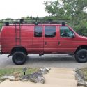
I am sure everyone is getting tired of seeing renderings of this design process, but I really think I am getting close to a finalized design and hoping this will be one of the final design revisions!
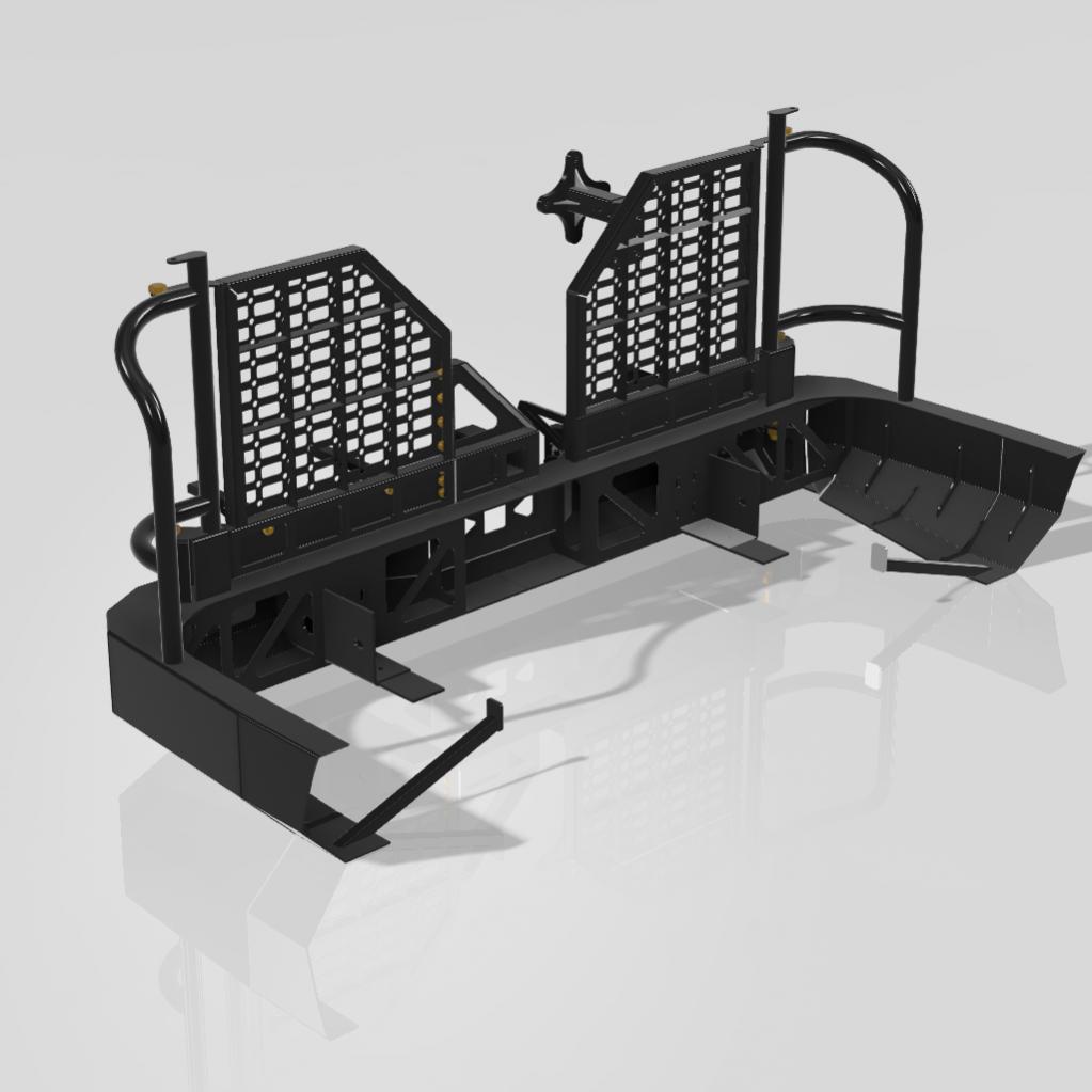
A few things that I have tweaked:- I remeasured the existing bumper mounting brackets and modeled them to better refine the mounting situation. The plan is to modify the factory mount to allow the mount to run further in on the outside and bottom of the frame rail utilizing the factory hitch mounting holes.
- After measuring the existing frame rails and mounts I realized that the main vertical face of the bumper was going to be slightly too short causing the bottom of the frame rails/mount to hang lower than the bumper's bottom edge. So I increased the height slightly making the bumper a bit chunkier but I think it still works with the front Aluminess bumper lines and keeps true to the original design.
- I revised the brush guard design to better fit around the lights by using a compound angle similar to the Aluminess design.
- I took the advice of boywonder and redesign the inner webbing of the bumper to minimize some of the the open areas of the bumper. I still have a fair amount of holes just to make it easier to access things like the light pods or the pivot bolt/nut but I think it's better than before. Also currently, the design is still using 3/16" so I still have holes to allow for weight reduction.
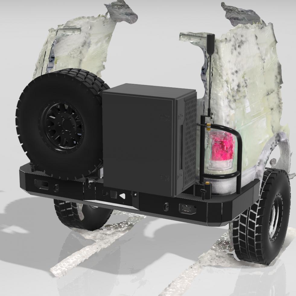
- I looked closer at how I plan on doing the pivot points and think I found a solution utilizing two dual tapered roller bearing setup with a bushing and a grade 8 3/4" bolt through the full assembly. (See the isometric section picture below).
- I again took the advice of boywonder and an upper pivot that ties into the brush guards with the possible option to tie those into the door hinges. This pivot can use a simpler bolt and bushing setup instead of a more complicated bearing system like the lower pivot.
- In adding the upper pivot I also redesigned the upper swing arms to allow them to better utilize the upper pivot point as well as cut out more weight of the panel by switching the design to a "MOLLE" pattern rather than just holes.
- I also added radio mounts on top of the brush guards for things like a weBoost antenna or a GMRS radio antenna. Probably not the most ideal spot for the best range but I would rather them blend in with the van and not stick up and above the roof line too far. Got to keep my garagability!
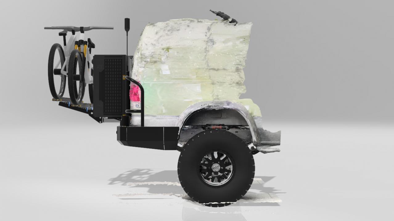
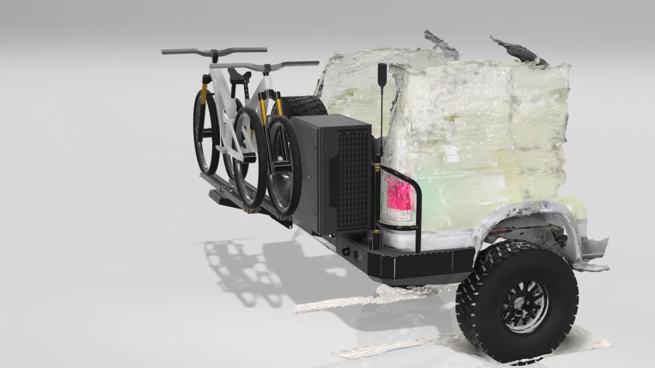
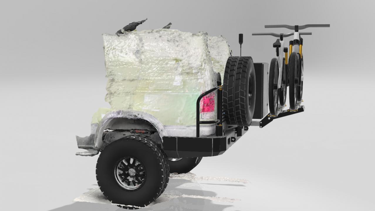
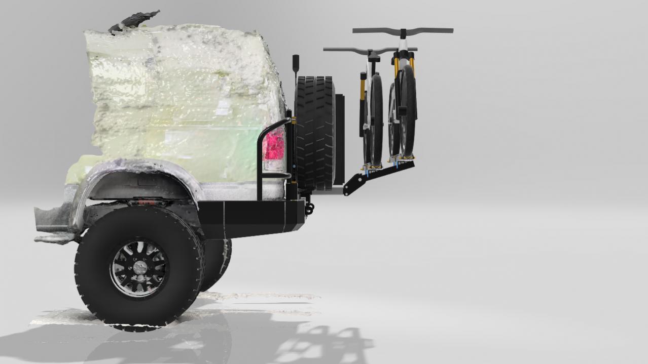
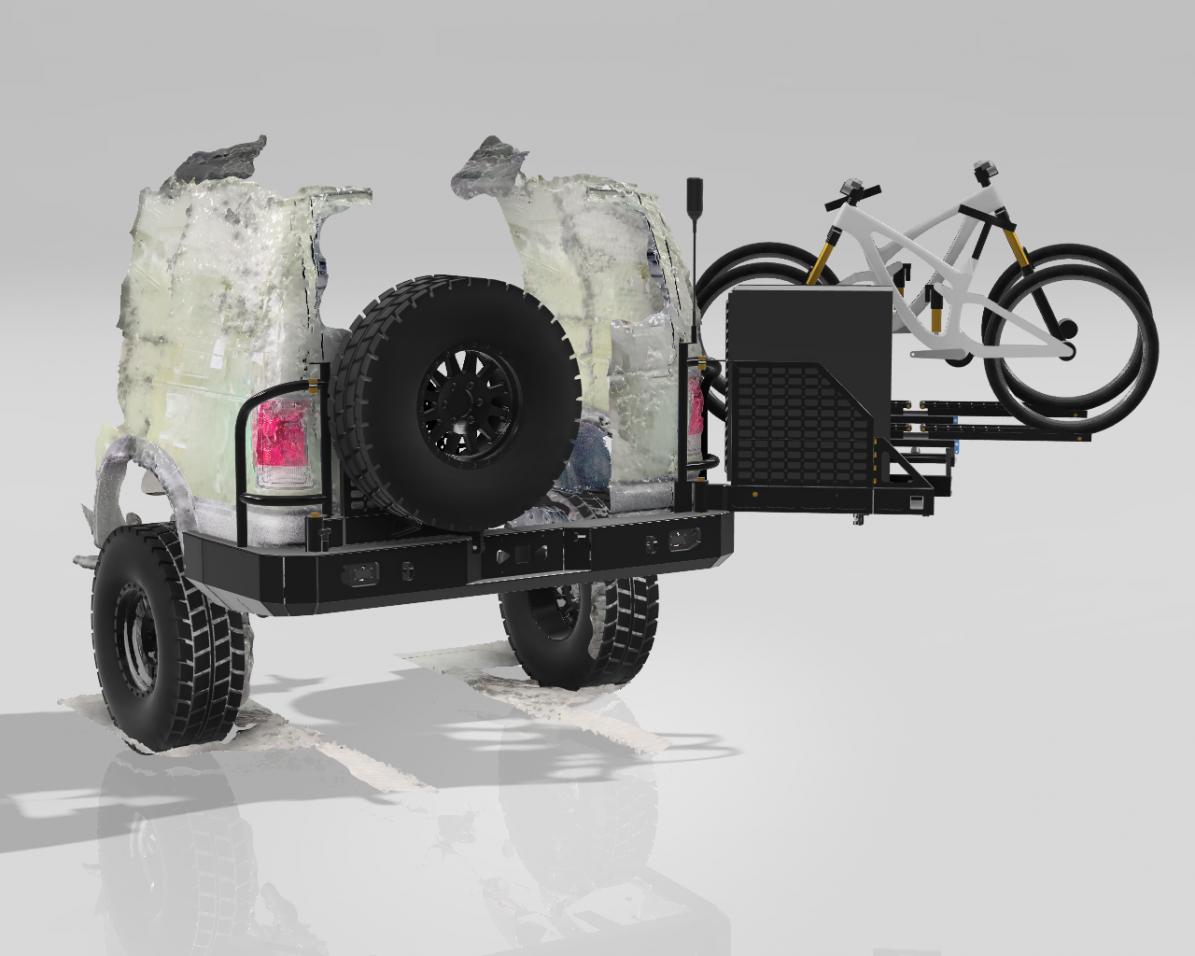
- The last thing that I added to the model just to better show the functionality of the bumper was my previously modeled 1up Bike rack and bikes just to test how far I can open the swing out. Based on this model it's over 150 degrees so not too bad!
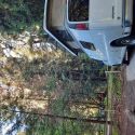
I have started doing some quick cardboard mock-ups just to confirm I am not screwing any dimensions up as it's a bit tricky to get the wrap around part dialed in with the contours of the body but I think I am close! Hopefully, all this time spent in the design phase will pay off in the end and make the construction stage of it much faster.
Thanks again to everyone who has been chiming in on this thread and giving me good tips/ideas. Hopefully, I'm not boring everyone with these endless revisions and some still believe that this will actually turn into a real world bumper and one day leave the modeling world!
Below are some pictures of the latest revision with the above changes incorporated. Let me know what you think and if you have any suggestions.
Bottom pivot isometric section cuts
Latest Revision:
W/ Bikes & Bike Rack On and Swing Open
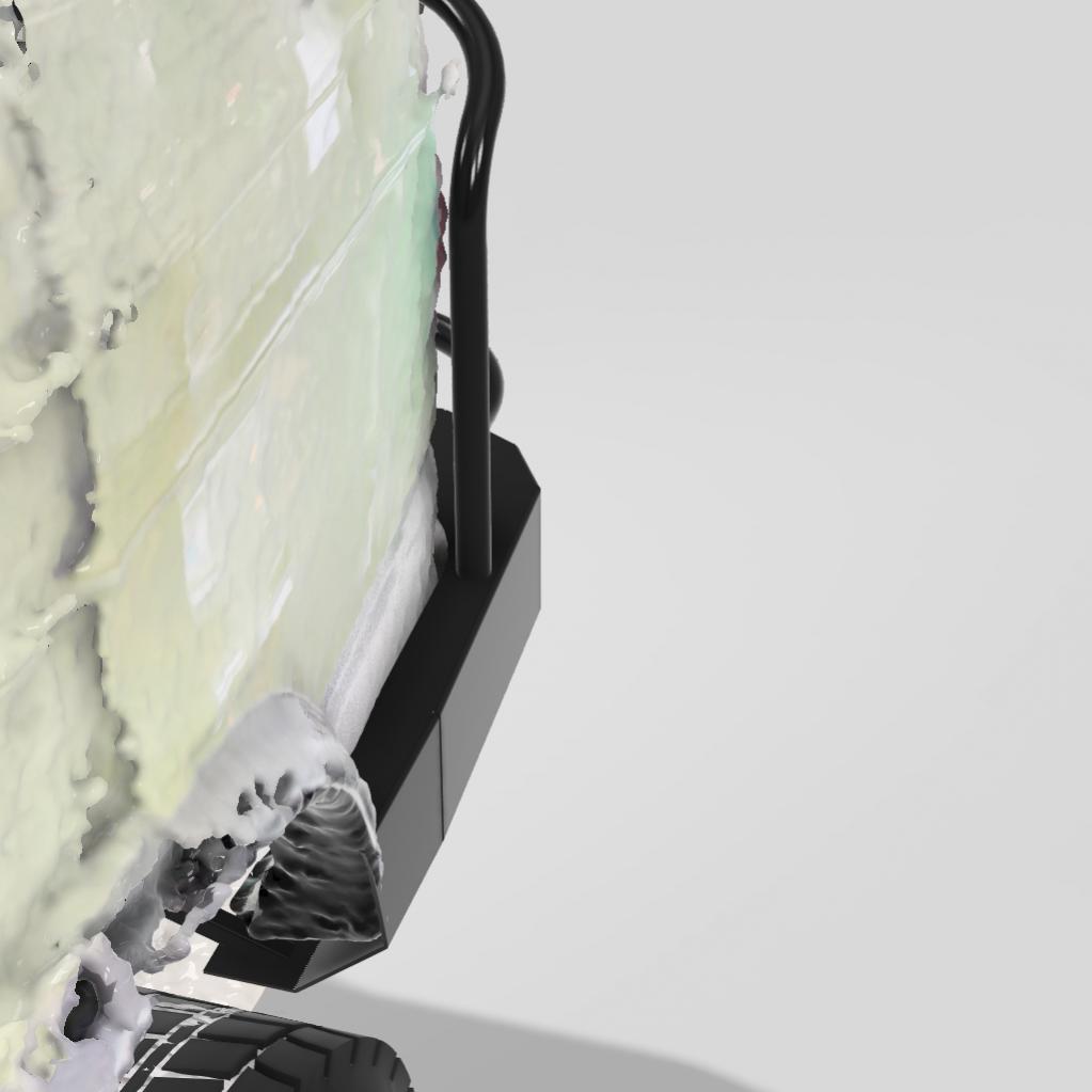
Bumper w/ Poor Quality 3D Scan


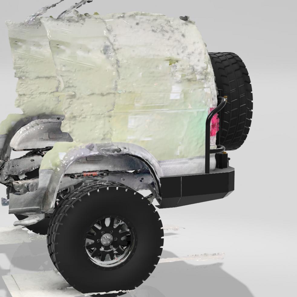
 This will still need to be capped at the wheel well and a rubber gasket will be installed between the bumper edge van body. Fender flares will be modified to die into the bumper.
Isolated Bumper Structure
__________________
Vandit - 2013 E250 Ground Up Build- Full Custom DIY Interior Build
- DIY U-Joint Off Road 6" 4x4 Conversion
|

|

|
|
03-25-2023, 09:35 PM
|
#72
|
|
Senior Member
Join Date: Jul 2013
Location: So Cal
Posts: 4,070
|
A few observations on your pivot joint.....
The long bolt will do wonders for extending the "wheelbase" of that joint for resisting bending moments.....although it still can move around a little.
Assuming you've got two tapered roller bearings in there.....
The nut at the very bottom is needed to retain everything while lengthening the joint, but it won't provide any preload for the lower bearing. As you tighten that nut it will just deflect/bend the sheet metal it's bearing against as well as the sheet metal under the lower tapered bearing...it will pull those two surfaces together.
If you can slip a sleeve around the bolt in there between the two sheet metal surfaces (or better yet weld one in there) you will have a much more robust joint and when you tighten the nut you will be able to meaningfully preload the tapered bearings. Properly preloaded bearings make a much stiffer design then bearings without much preload.
You could also put a sleeve around the bolt between the two bearings; with the length of the sleeve slightly less than distance between the two inner bearing races, this will limit bearing damage from over-tightening the bolt, although I don't think that will be much of an issue if you use large wheel bearing sized Timkens. Getting the sleevelength correct can be a very exacting exercise, so you are likely better off just not overtightening.
__________________
2008 E350 RB passenger 4WD SMB penthouse
2013 KTM 350 EXC
2008 KTM 250 XCF-W
2003 Honda Element
|
|
|
|
|
03-25-2023, 10:09 PM
|
#73
|
|
Senior Member
Join Date: Feb 2020
Location: Bend, OR
Posts: 307
|
Quote:
Originally Posted by boywonder

A few observations on your pivot joint.....
The long bolt will do wonders for extending the "wheelbase" of that joint for resisting bending moments.....although it still can move around a little.
Assuming you've got two tapered roller bearings in there.....
The nut at the very bottom is needed to retain everything while lengthening the joint, but it won't provide any preload for the lower bearing. As you tighten that nut it will just deflect/bend the sheet metal it's bearing against as well as the sheet metal under the lower tapered bearing...it will pull those two surfaces together.
If you can slip a sleeve around the bolt in there between the two sheet metal surfaces (or better yet weld one in there) you will have a much more robust joint and when you tighten the nut you will be able to meaningfully preload the tapered bearings. Properly preloaded bearings make a much stiffer design then bearings without much preload.
You could also put a sleeve around the bolt between the two bearings; with the length of the sleeve slightly less than distance between the two inner bearing races, this will limit bearing damage from over-tightening the bolt, although I don't think that will be much of an issue if you use large wheel bearing sized Timkens. Getting the sleevelength correct can be a very exacting exercise, so you are likely better off just not overtightening.
|
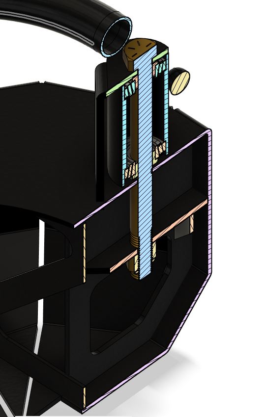
Thanks for pointing that out, that was a silly oversight! I will for sure be adding in a welded sleeve there as you said. I can't remember off the top of my head what size bearing I pulled from the McMasters catalog, but from what I remember it should be way over spec'd for this application, but adding in an additional sleeve between the two might be a good idea if I can get it precise enough.
Thanks again for pointing that out and for all your input throughout this! It's much appreciated.
__________________
Vandit - 2013 E250 Ground Up Build- Full Custom DIY Interior Build
- DIY U-Joint Off Road 6" 4x4 Conversion
|
|
|
|
|
03-26-2023, 08:49 AM
|
#74
|
|
Senior Member
Join Date: Jul 2013
Location: So Cal
Posts: 4,070
|
Quote:
Originally Posted by aarcaris
Thanks for pointing that out, that was a silly oversight! I will for sure be adding in a welded sleeve there as you said. I can't remember off the top of my head what size bearing I pulled from the McMasters catalog, but from what I remember it should be way over spec'd for this application, but adding in an additional sleeve between the two might be a good idea if I can get it precise enough.
|
If you add a sleeve between the inner races so that you could tighten up the entire stack the sleeve would need to be slightly shorter than then space between the inner races..on the order of .001" or thereabouts (without doing the math).....not really practical here. If the sleeve is too long the bearings won't be preloaded at all after tightening, and too short you may Brinell (damage) the bearings if over tightened.
A more common way that it's done it to put wave washers between the outer races and the shoulders that they bear against and have a solid sleeve around the shaft for the inner races. The allows tightening the joint so that the wave washers compress some when the inner races sandwich the sleeve tightly. Basically it increases compliance in the stack so that you don't have to machine things with super tight tolerances. It also prevents the possiblity of Brinelling the bearings if over tightened.
Tapered roller bearings are much more resistant to Brinelling since they have line contact with the races as opposed to point contact with ball bearings, so you should be able to tighten the joint enough to get a robust/stiff setup without much risk of harming the bearings without a sleeve between the inner races. You will need the lower sleeve in there though.
__________________
2008 E350 RB passenger 4WD SMB penthouse
2013 KTM 350 EXC
2008 KTM 250 XCF-W
2003 Honda Element
|
|
|
|
|
03-27-2023, 09:52 AM
|
#75
|
|
Senior Member
Join Date: Feb 2020
Location: Bend, OR
Posts: 307
|
Quote:
Originally Posted by boywonder
If you add a sleeve between the inner races so that you could tighten up the entire stack the sleeve would need to be slightly shorter than then space between the inner races..on the order of .001" or thereabouts (without doing the math).....not really practical here. If the sleeve is too long the bearings won't be preloaded at all after tightening, and too short you may Brinell (damage) the bearings if over tightened.
A more common way that it's done it to put wave washers between the outer races and the shoulders that they bear against and have a solid sleeve around the shaft for the inner races. The allows tightening the joint so that the wave washers compress some when the inner races sandwich the sleeve tightly. Basically it increases compliance in the stack so that you don't have to machine things with super tight tolerances. It also prevents the possiblity of Brinelling the bearings if over tightened.
Tapered roller bearings are much more resistant to Brinelling since they have line contact with the races as opposed to point contact with ball bearings, so you should be able to tighten the joint enough to get a robust/stiff setup without much risk of harming the bearings without a sleeve between the inner races. You will need the lower sleeve in there though.
|
Okay, that makes perfect sense! I think as you said then no inner sleeve for this one maybe just added washers to help. I appreciate the explanation of everything on this.
__________________
Vandit - 2013 E250 Ground Up Build- Full Custom DIY Interior Build
- DIY U-Joint Off Road 6" 4x4 Conversion
|
|
|
|
|
03-27-2023, 12:25 PM
|
#76
|
|
Senior Member
Join Date: Jun 2018
Posts: 130
|
Random ideas sparked from boy wonder's comments...
how about using two wheel bearings in opposite directions to each other, looking like a sand clock with conical sleeves on each side for the arm and a bolt that passes through to tighten the stack? you could even tap a zerk in
|
|
|
|
|
03-27-2023, 12:53 PM
|
#77
|
|
Senior Member
Join Date: Feb 2020
Location: Bend, OR
Posts: 307
|
Quote:
Originally Posted by lashidalgo
Random ideas sparked from boy wonder's comments...
how about using two wheel bearings in opposite directions to each other, looking like a sand clock with conical sleeves on each side for the arm and a bolt that passes through to tighten the stack? you could even tap a zerk in
|
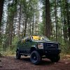
If I am understanding correctly that is basically the idea that I am going for. I may have not explained it, or shown it very well, but here are a few examples of what I am trying for that I found online.
 This is the product I had first looks at
 This is similar to what I used on my last bumper.
 This is an exploded ISO I found in the installation instructions of a 4Runner C4 swing out bumper.
__________________
Vandit - 2013 E250 Ground Up Build- Full Custom DIY Interior Build
- DIY U-Joint Off Road 6" 4x4 Conversion
|
|
|
|
|
03-27-2023, 12:57 PM
|
#78
|
|
Senior Member
Join Date: Jun 2018
Posts: 130
|
Quote:
Originally Posted by aarcaris
|
YES you got it!
|
|
|
|
|
03-13-2024, 01:44 PM
|
#79
|
|
Senior Member
Join Date: Feb 2020
Location: Bend, OR
Posts: 307
|
Pretty wild to see that it's been almost a year since I last posted on this thread! I put this project on the back burner for a while as I was busy with other things, and the fabricator who was going to help me was occupied as well. On the first of the year, I started reaching back out to my fabricator to see if he had time, but unfortunately, it doesn't seem like he's going to be able to take on this project anymore. So, I started back in my search for someone who could do it, and luckily, I think I have someone all lined up to start on it in the next couple of weeks. So, I am keeping my fingers crossed that things work out, and I'll have some updates to share soon!
__________________
Vandit - 2013 E250 Ground Up Build- Full Custom DIY Interior Build
- DIY U-Joint Off Road 6" 4x4 Conversion
|
|
|
|
|
03-13-2024, 02:32 PM
|
#80
|
|
Senior Member
Join Date: Oct 2009
Location: Portland, OR
Posts: 1,257
|
Quote:
Originally Posted by aarcaris
Pretty wild to see that it's been almost a year since I last posted on this thread! I put this project on the back burner for a while as I was busy with other things, and the fabricator who was going to help me was occupied as well. On the first of the year, I started reaching back out to my fabricator to see if he had time, but unfortunately, it doesn't seem like he's going to be able to take on this project anymore. So, I started back in my search for someone who could do it, and luckily, I think I have someone all lined up to start on it in the next couple of weeks. So, I am keeping my fingers crossed that things work out, and I'll have some updates to share soon!
|
Looking forward!
__________________
2001 Ford RB 7.3 Quadvan (sold)
2006 Sportsmobile EB Transformer 6.0
|
|
|
|
|
|
 Posting Rules
|
You may not post new threads
You may not post replies
You may not post attachments
You may not edit your posts
HTML code is Off
|
|
|
|
 » Recent Threads
 |
|
|
|
|
|
|
|
|
|
|
|
|
|
|
|
|
|
|
|
|
|
|
|
|
|
|
|
|
|
|
|
|
|


 Vandit
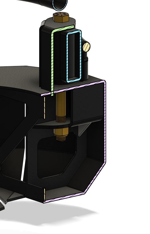


 Vandiesel II
 Linear Mode