|
|
 01-20-2023, 08:02 AM
|
#51
|
|
Senior Member
Join Date: Sep 2013
Location: Georgia
Posts: 734
|
I'm certainly no structural engineer - but please keep in mind - torque - torque - torque on the metal joints, weld points, etc. Nothing like fractured/busted weld joints on a bike rack or fuel "caddy" when bouncing around on the back roads !
|

|

|
|
01-23-2023, 10:23 AM
|
#52
|
|
Senior Member
Join Date: Feb 2020
Location: Bend, OR
Posts: 307
|
Quote:
Originally Posted by WillTheThri11

Following along, this is awesome! I've been looking around for a fabricator who can build exactly this style bumper. Similar to the "high clearance bumpers" that a lot of Toyotas use. I would need it adapted for the EB and I want to make sure that side part is strong enough to act as a rock slider. What software are you using?
|
Yeah, Toyota High clearance bumpers were a Big inspiration for this design. Still in the process of working through drawings and analysis of how best to build something that isn't ungodly heavy, but will look and work the way I want. This was all done in an architectural program called Revit, which is 100% the wrong program to use. It's what I am most used to so that's where I started but I am now working on redesigning it in Fusion 360 so I can have better analysis tools and better integration with things like CNC machines. Also for rendered views/animations, I exported my model to Twinmotion as it gives better visual control of the elements.
Quote:
Originally Posted by doublevan2
I'm certainly no structural engineer - but please keep in mind - torque - torque - torque on the metal joints, weld points, etc. Nothing like fractured/busted weld joints on a bike rack or fuel "caddy" when bouncing around on the back roads !
|
Yeah, there are a lot of forces at work that will need to be taken into account for this kind of design. Still working through the best way to do the swingouts and will most likely try to do some stress analysis in the model before any final decisions for the bumper. What I know for sure is it going to need to be tied into the frame in a few spots rather than the typical 2 bumper mounting points to ensure enough rigidity.
__________________
Vandit - 2013 E250 Ground Up Build- Full Custom DIY Interior Build
- DIY U-Joint Off Road 6" 4x4 Conversion
|
|
|
|
|
01-23-2023, 11:55 AM
|
#53
|
|
Senior Member
Join Date: Sep 2021
Location: Southern California
Posts: 113
|
I have solidworks if you need any help with anything, let me know...also where did you get the van CAD from...is there one for the extended model?
|
|
|
|
|
01-23-2023, 02:25 PM
|
#54
|
|
Senior Member
Join Date: Feb 2020
Location: Bend, OR
Posts: 307
|
WillTheThri11: Will do! I couldn't find a good CAD file when I started on my interior design so I actually used the Ford Body Builder book to build a rough file from scratch. Over the last few years, I have tweaked that file to be better for me, but it is still fairly rough. It looks decent, but is not 100% accurate.
__________________
Vandit - 2013 E250 Ground Up Build- Full Custom DIY Interior Build
- DIY U-Joint Off Road 6" 4x4 Conversion
|
|
|
|
|
03-09-2023, 04:42 PM
|
#55
|
|
Senior Member
Join Date: Feb 2020
Location: Bend, OR
Posts: 307
|
Update:
Okay, so it's been a bit since I posted anything about the Bumper project. As some of you may have seen on my main build thread ( Vandit Build Thread) I was pretty occupied for a while getting my 4x4 conversion finished up. Now that I have finished that and have taken some time off from focusing on a big project I have started to dive back into the bumper build.
When I last posted about the bumper build I was still in the planning/design stage, and unfortunately, I still havent moved much past that! There is a good reason for that though. I have started trying to teach myself some new software that is going to work much better for getting some workable parts and files that can hopefully better communicate with machines like CNCs and laser cutters. So I began re-modeling my original design in Fusion360. Its been a slow process to learn, and I feel very much like I dont know what I am doing but its been a fun exercise and I think overall it has helped me get a better design going. It has brought some problems to light and has helped me make a more real world workable design.
So a few things that have shifted from the previous design iteration.
- I have decided to make it out of steel rather than aluminum. There are a few reasons for this, but the main one is cost. Even with this being out of steel I think it's going to be a pricey bumper. My current plan is to have the same fabricator who did my sliders help me build the bumper as he is a great fabricator and has access to lots CNCs, press brakes, and more.
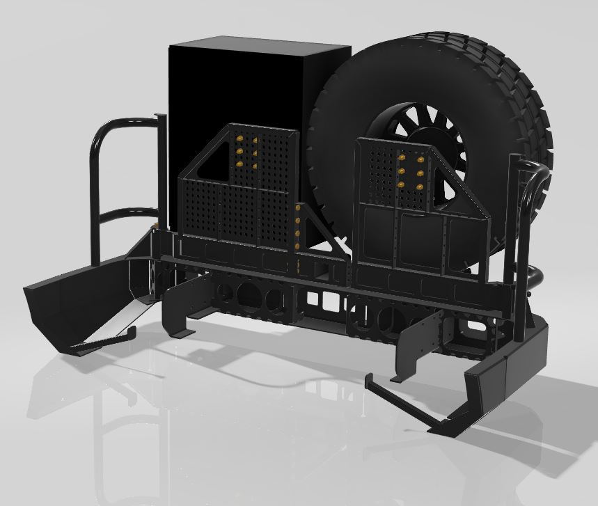
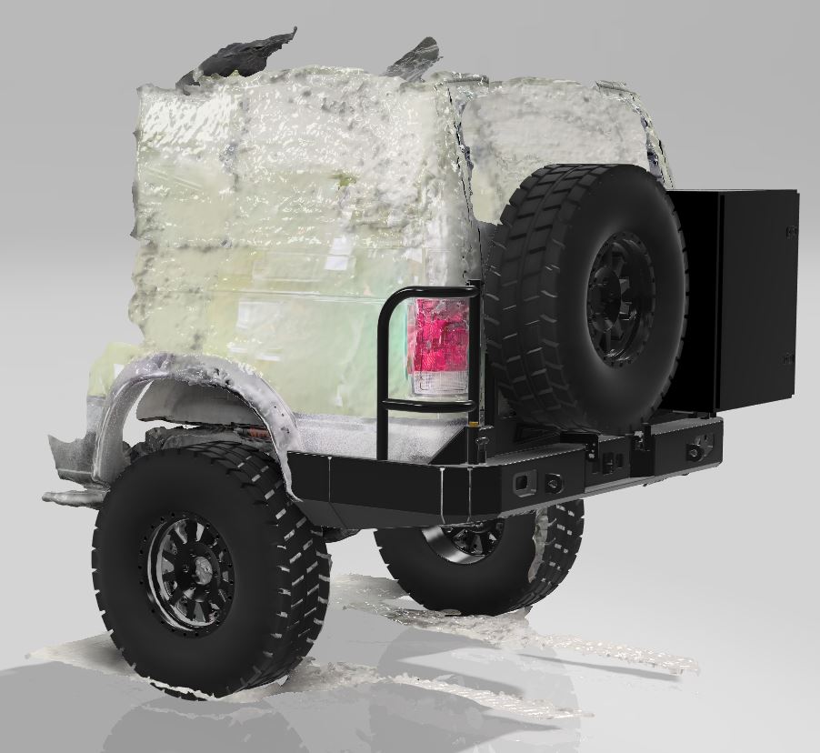
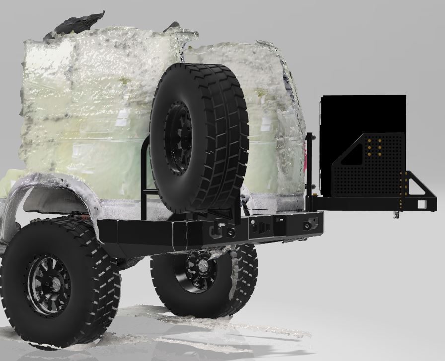
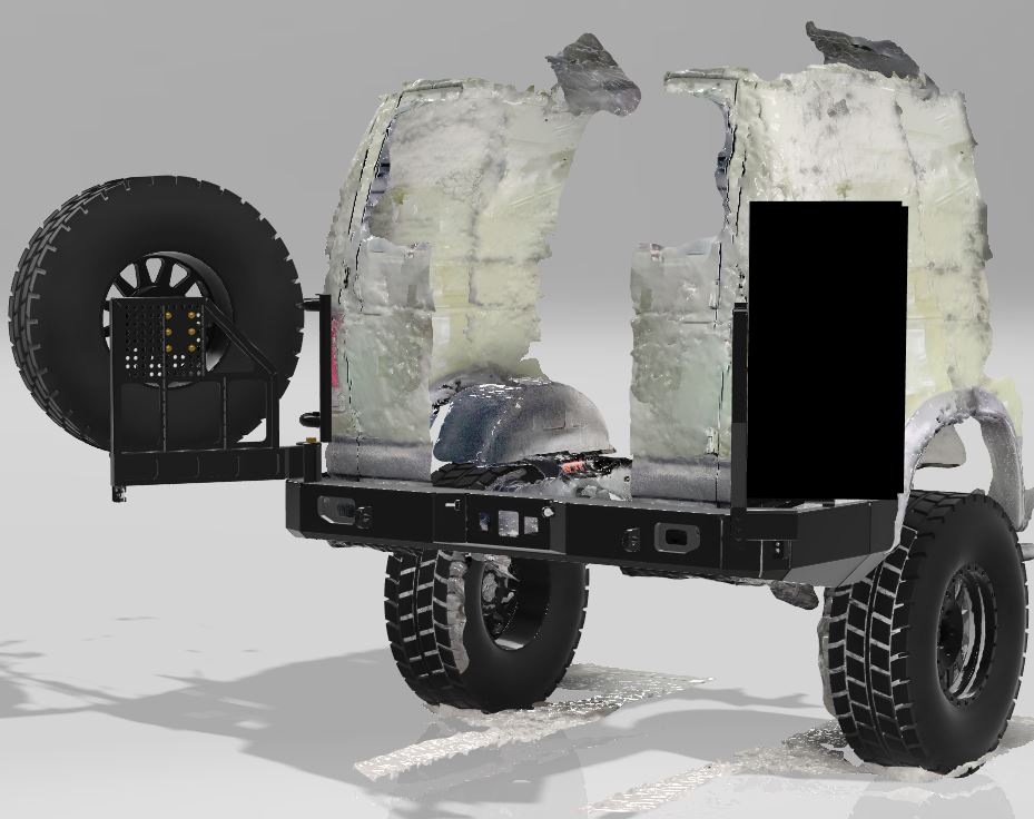
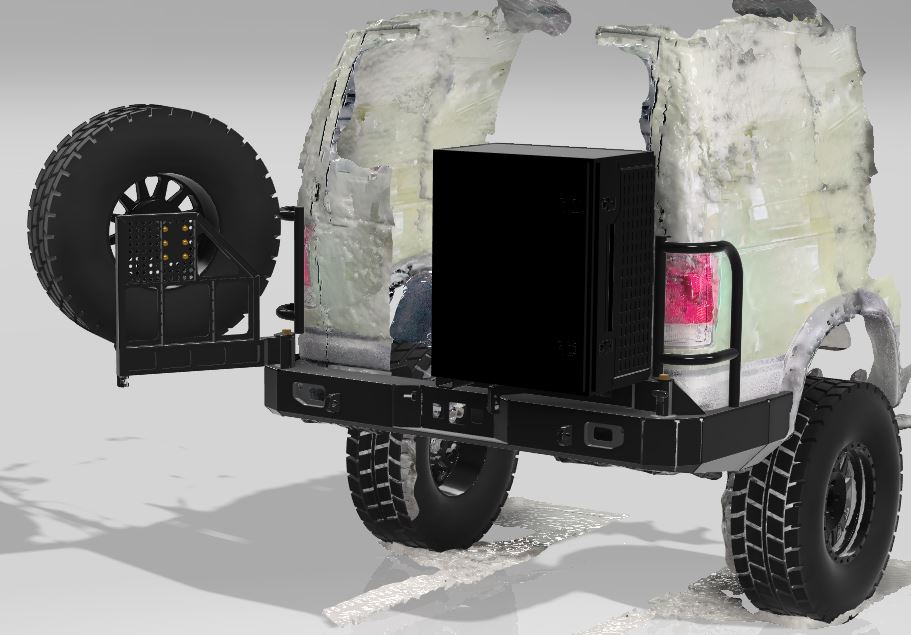
- I have eliminated the idea of a storage box within the structure of the bumper as I think it would yield a very minimal amount of storage and would overly complicate the design. Instead, I will most likely add a center skid (where the factory spare sits) where I can mount my air tank and compressor and can maybe come up with a system to utilize that area as extra storage if need be.
- I changed the swing arm designs to hopefully help make them lighter and stronger by using sheet metal that is bent and welded rather than a square tube structure that I had before.
- I changed the pivot design as I felt like I wasn't going to get enough strength out of the small bolt design similar to what Aluminess does. So I currently am planning on using a Carrier Hinge Bearing system (Link) that should give lots of rigidity and strength to the swingouts. (This was another driving factory for steel construction. I have yet to see one of these pivots out of aluminum.)
- I am sure there are some more tweaks, but these are the main ones I can think of right now.
I feel like I am getting closer to actually having a ready to go design to start building, but still have a few things to dial in. I am hopeful that I will have the dimensions 100% in the next week or so and then hope to start getting things going on this within the next couple of weeks. The ultimate goal is to have it completed by the middle of May or at the latest by June.
Below are some updated renderings of the new design if anyone is interested in it. Please excuse the very crappy low quality 3D scan of the rear of my van. It was a quick scan done with my phone just as a test to see how things were stacking up. It's not a good scan but at least it gets the point across.
__________________
Vandit - 2013 E250 Ground Up Build- Full Custom DIY Interior Build
- DIY U-Joint Off Road 6" 4x4 Conversion
|
|
|
|
|
03-09-2023, 06:19 PM
|
#56
|
|
Senior Member
Join Date: Sep 2021
Location: Southern California
Posts: 113
|
Looks great...nice that you could import a 3D scan of the van. How did you do that btw? Wondering if I can do this in SolidWorks. Any particular reason you are mounting the bumper on the frame rails vs the stock bumper flanges? Another thought, you may need to box in the "slider" portion from the wheel-well back so it doesn't crush if/when you come down on a rock...Probably also want that square tubing to be same size as your sliders were.
|
|
|
|
|
03-09-2023, 06:25 PM
|
#57
|
|
Senior Member
Join Date: Sep 2021
Location: Southern California
Posts: 113
|
one more thought...you may want to include a cutout and maybe that could double as a hi-lift jacking point...only trying to help take my suggestions or leave them...I love this project!
|
|
|
|
|
03-09-2023, 08:16 PM
|
#58
|
|
Senior Member
Join Date: Dec 2014
Location: Riverside Ca.
Posts: 740
|
Your pics and idea are great. The main thought should be focused on what kind of wheeling you will do. If you doing beach and 1 to 2 out of 5 trails then you can load and add all you want. With that said your accessories will only be your challenge which ones and where to put them. Sometimes we can over think things.
|
|
|
|
|
03-10-2023, 08:26 AM
|
#59
|
|
Senior Member
Join Date: Jul 2013
Location: So Cal
Posts: 4,070
|
This iteration looks very nice!
Can you calculate the weight in Fusion360? I'm unclear what Fusion360 offers that Solidworks doesn't......other than it's lots more affordable.
...a couple of comments......
The spindles for the swingarms are going to see large bending moments. Have you played with an aluminess setup that has stuff in the box? Open and close either swingarm, there is a lot of weight cantilevered out there on both sides.
When closed, Aluminess has delrin ramps that help support the arms screwed into the top of the bumper, I did a similar thing.
I would have the spindles extend down through the bumper and welded to the lower bumper surface, you will need that extra "wheelbase" for stiffness.
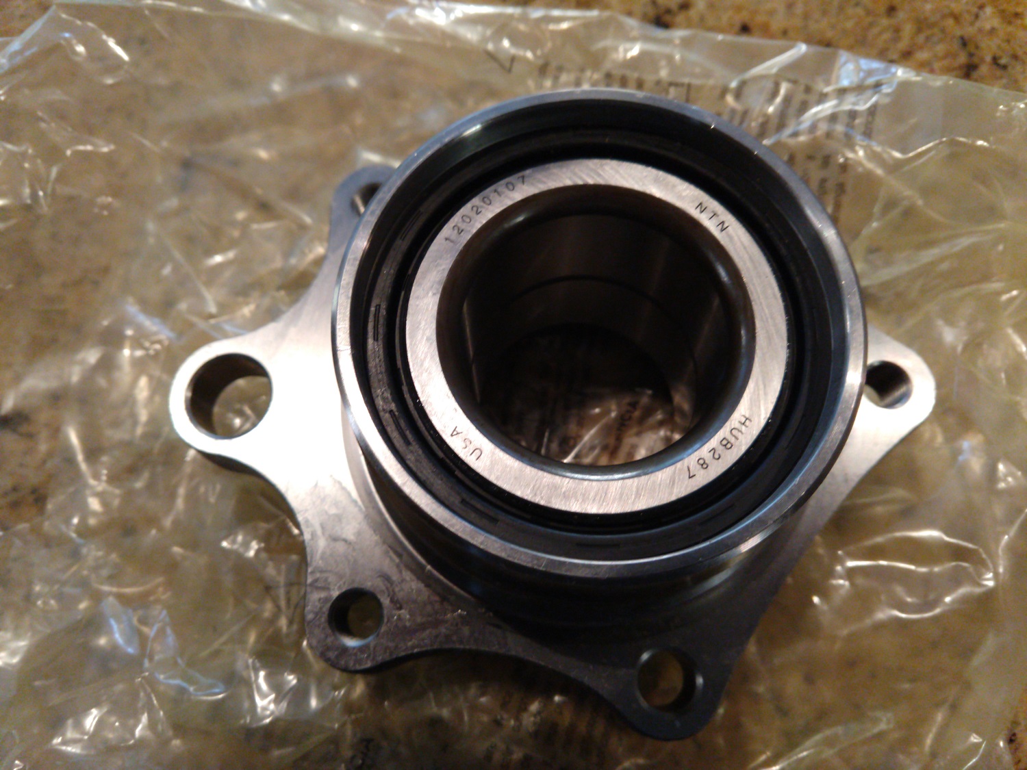
It may have been discussed in my bumper thread (can't remember) but you could consider using some modern "unit bearing" assemblies from front or rear hubs as the spindle support. They are kind of perfect for this, a dual row set of beefy bearings in a flanged hub with holes in the flange.
I see you have a stiffener across the rear section of the bumper, but you still have a fair bit of open cross section. If you can box in more of the cross section that will increase your section modulus a lot.
I would also triangulate the flanged spare tire support for added stiffness.
__________________
2008 E350 RB passenger 4WD SMB penthouse
2013 KTM 350 EXC
2008 KTM 250 XCF-W
2003 Honda Element
|
|
|
|
|
03-10-2023, 08:44 AM
|
#60
|
|
Senior Member
Join Date: Jul 2013
Location: So Cal
Posts: 4,070
|
__________________
2008 E350 RB passenger 4WD SMB penthouse
2013 KTM 350 EXC
2008 KTM 250 XCF-W
2003 Honda Element
|
|
|
|
|
|
| Thread Tools |
|
|
| Display Modes |
 Linear Mode Linear Mode
|
 Posting Rules
|
You may not post new threads
You may not post replies
You may not post attachments
You may not edit your posts
HTML code is Off
|
|
|
|
 » Recent Threads
 |
|
|
|
|
|
|
|
|
|
|
|
|
|
|
|
|
|
|
|
|
|
|
|
|
|
|
|
|
|
|
|
|
|


 Vandit