Journey with Confidence RV GPS App RV Trip Planner RV LIFE Campground Reviews RV Maintenance Take a Speed Test Free 7 Day Trial ×


Reply
 
Thread Tools Display Modes
 
Old 02-08-2017, 12:39 PM   #1
Member
 
Join Date: Oct 2016
Location: Tampa FLorida
Posts: 41
DIY Converting a manual penthouse to electric (A possible solution?)

I have recently installed my EB penthouse on my Van. The penthouse was a junkyard find and all the work was done by yours truly. It works, It fits, Its water tight. However, Its heavy. Very Heavy. I Can lift it and lower it unloaded, but my girlfriend cannot. I am a healthy 25 year old male and this thing is still hard for me. I can get the top up and down just fine unloaded, but when I added my empty thule cargo box with load bars (~40lbs) to the rear I about pulled a hernia getting it up. I havent even tried loading it or adding my solar panels. I know the panels up front will distribute the load better. they weigh about 10 more pounds than the empty box, but I would like to be able to add about 20#-30# worth of stuff in the box. EIther way I want my girlfriend (and the person who buys the van when Im done) to be able to easily lift and lower the penthouse.

I have made a number of modifications to the penthouse that I thought would make it smooth and easy.
  • Sleeved the bars(per recommendation of Boywonder)
  • Shoulder bolts
  • removed 3 links from the chain
  • greased everything up
The only thing I havent done is add a small block behind the assist spring. While I had everything apart I took some time to run some tests on the springs and make some free body diagrams. The large spring has a value of 14#/inch with an initial pull requiring 45#. The small assist spring has a value of 40#/inch. I dont know if this is true for any other EB penthouse than mine. My penthouse came from Austin in the mid 90s.

I know sportsmobile can modify the penthouses for you, but I dont have $3500 to blow. I dont think they would take me anyways because I did the install myself.

So I went went back to the drawing board and this is what I came up with.


Everyone be nice 
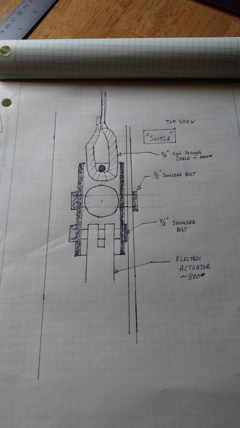
I havent drawn something so technical in a while. Its not exact but I hope you understand what Im going for here. I want to use an electric actuator and make a small "shuttle" that will carry the lifting arm forward. The chain will be replaced with a high strength steel cable that will be brought inline center and lay flat under neath the bar when closed. This is where it goes :


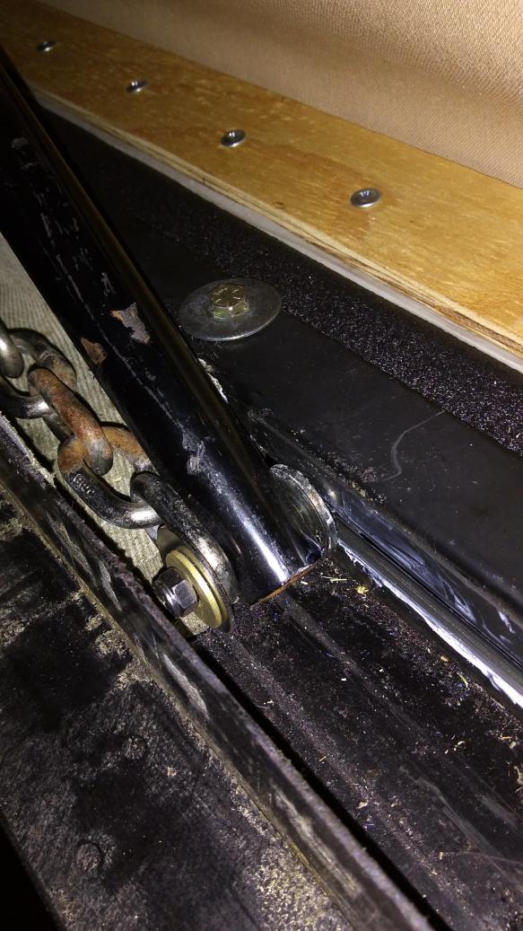
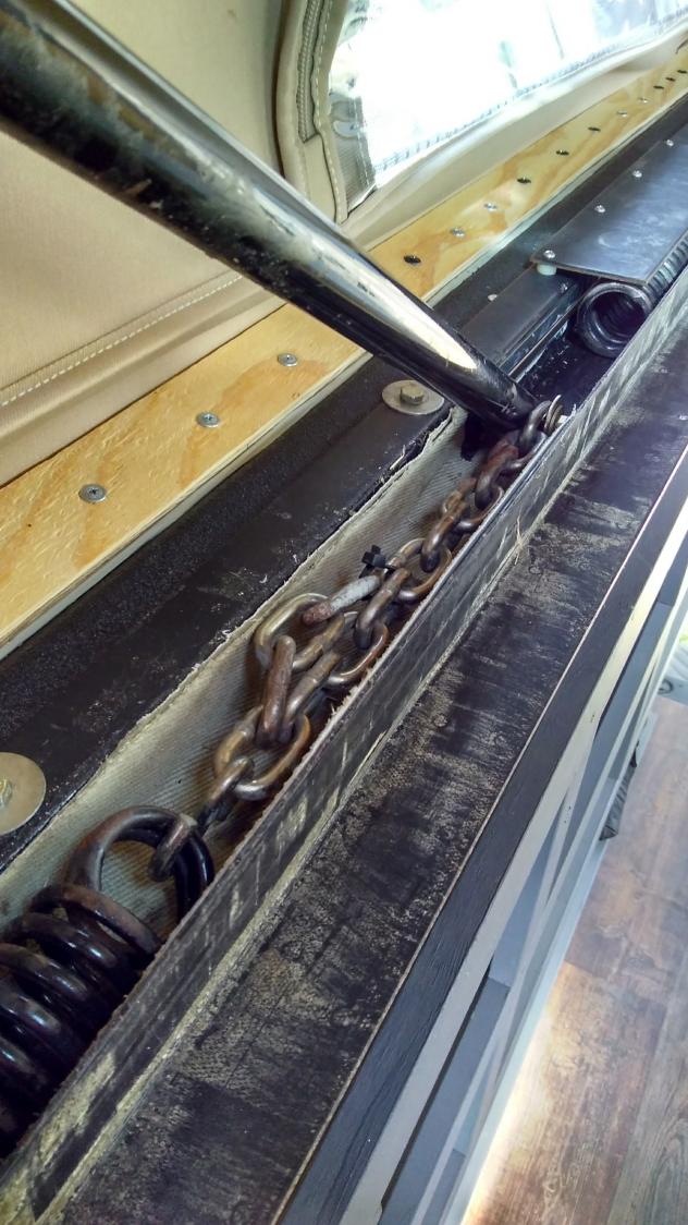
This is perhaps the most important and my least favorite thing about the penthouse design. With the chain on the outside of the bar it creates a lot of torsion and friction around the guided track its supposed to keep it in line. I believe friction is working strongly against me here. I wanted to redesign it before the install, but decided against it.

The "shuttle" will replace and center this design entirely and get rid of the small assist spring (the large spring remains). It will be made out of either high strength 1/4" thick 1-1/2" square tube by me, or sent out to be CNC milled. The biggest problem with this design, is moving the chain on center. When the top is lowered the bars lay down to 5 degrees and would contact the chain. This is why I want to use a steel cable that lays flat. I would likely have to make the shuttle longer and space the cable away from the bar. This would allow me enough room to bolt it in vertically.


This is the actuator that I have found that I think is best suitable for this application. I want to use the PA-11 D50 model in 24v with an 1100# thrust. It will go where the assist spring is currently. With a diameter of about 2" it will be a near perfect fit. A 12" model with collaspased length of ~25" will fit nearly perfect in the 28" I have available inside the track. I do not like the 12v model becasue of conflict with duty cycle and speed. At 0.05" per second under load it would take nearly 4 minutes to extend the 12" needed. With a duty cycle of 2 minutes I would have to wait 8 minutes once halfway up before continuing the lift. 12 minutes to lift the top is not happening.

I spoke with a product engineer and he assured me I could use a voltage step up 12v to 24v module if I met the app requirements. 5A per actuator. Amazon sells a 12v to 24v Step up with 20A rating. for under $50. With the 24v model I could lift the top in under 2 minutes with no pause for cool down.

The 1100# model sounds like extreme overkill for lifting the top, but Im actually concerned it wont be enough. The reason for this is when the top is down the bars are only 5 degrees above normal. This means that for every 100# of force along the normal line, only 8.7# will be translated into the upward direction. Which means the 1100# model give me a vertical force 95.9# per actuator or 191.7# for the pair. Once the top begin to move and the angle of the bars opens up, the 1100# will be much more than sufficient to get it all the way up and keep it up. Its the initial lift that has me hesitant, considering I plan on adding an additional 100# to the roof.


This has me thinking; if something like this would work, why isnt sportmobile doing it? Considering you wont meed to remove the top and material cost would be around $600.

I know there are a few engineers (Or guys that act like it) on this forum and some input would be appreciated. I know there are alot of your that would be more than happy for me to be the guinea pig on this one, but I want to think it through before dropping the cash and doing the work. I would really like to see this work, not just for my sake, but my girlfriend, and all the other guys I know are struggling getting it up and down (No pun intended )

Product links:
https://www.actuatorzone.com/mini-tube-linear-actuator Open the PDF

https://www.amazon.com/uxcell-Conver...4v+step+up+20A

https://www.mcmaster.com/#standard-wire-rope/=169mk0o

Flakwagon is offline   Reply With Quote
Old 02-08-2017, 01:09 PM   #2
Senior Member
 
rallypanam's Avatar
 
Join Date: Feb 2013
Location: San Francisco/Nevada City
Posts: 3,769
Beyond me, but I like the idea!
rallypanam is offline   Reply With Quote
Old 02-08-2017, 01:37 PM   #3
Senior Member
 
larrie's Avatar
 
Join Date: Apr 2011
Location: Oregon Ciry Oregon
Posts: 2,854
There are a couple of solution to help raise a manual penthouse top. Remember. all you need to do is get it started, then the springs take over.

LenS posted this thread about using a jack screw, http://www.sportsmobileforum.com/for...cks-17617.html. An upgrade to this would be to use an cordless electric to drive the screw.

We used a cargo bar as a jacking solution. It worked very well. All we needed to do is get the top started, about 25 clicks and then it was easy to push up.

Your solution looks promising too.
__________________
Larrie
Read detailed trip reports, see photos and videos on my travel blog, luinil.com.
Current van: 2002 Ford E350 extended body camper with Colorado Camper Van pop top and Agile Offroad 4WD conversion.
larrie is offline   Reply With Quote
Old 02-08-2017, 02:37 PM   #4
Member
 
Join Date: Oct 2016
Location: Tampa FLorida
Posts: 41
Thanks Larrie, I am familiar with both of these options and the portable electric lift. All of which would likely work. But I would rather not haul around a big chunky tool that only serves one purpose. Maybe a hi lift jack would work and be useful otherwise. I still want a solution that doesn't require a "trick" to use. If this electric doesn't pan out then I'll be going into ideas like this.
Flakwagon is offline   Reply With Quote
Old 02-08-2017, 04:42 PM   #5
Senior Member
 
boywonder's Avatar
 
Join Date: Jul 2013
Location: So Cal
Posts: 4,072
Flakwagon: keep going!! excellent idea! I'll read this again and give it some thought.

Cable is a good idea too except you have a lot riding on the crimp that makes the loop....

Not entirely clear on why you need to get the chain out of the way..can't the actuators just go where the helper springs are sitting?
__________________
2008 E350 RB passenger 4WD SMB penthouse
2013 KTM 350 EXC
2008 KTM 250 XCF-W
2003 Honda Element
boywonder is offline   Reply With Quote
Old 02-08-2017, 04:56 PM   #6
Senior Member
 
boywonder's Avatar
 
Join Date: Jul 2013
Location: So Cal
Posts: 4,072
OK...a couple of thoughts....

Does anyone know what and RB or EB top weighs? No guessing here....actually weigh a top....

Next thought......can you roughly determine the compressed length of the helper springs with the top down? you may be able to closely estimate by looking at the wear marks on the track.

You already determined the rate of the helper springs, once you know the compressed length you can determine the load when the top is down.....

Then lift the top while standing on a bathroom scale and get that reading.

Work that backwards with a little trig (like you already did) to determine how much additional force you need to apply to the helper spring to get the top up. This number will be lots bigger than the scale reading......

Add those two forces together and hope that they are less than 1100 lbs....

This will give you an idea of how much extra force (margin) that you have in the design.

I'm loving the shuttle design as well....any reason that the lower shoulder screw in the sketch cannot also ride in the slot in the rail? Would provide more "wheelbase" for additional stability.

We can use the weight of the top to check our math....
__________________
2008 E350 RB passenger 4WD SMB penthouse
2013 KTM 350 EXC
2008 KTM 250 XCF-W
2003 Honda Element
boywonder is offline   Reply With Quote
Old 02-08-2017, 05:33 PM   #7
Member
 
Join Date: Oct 2016
Location: Tampa FLorida
Posts: 41
Quote:
Originally Posted by boywonder View Post
OK...a couple of thoughts....

Does anyone know what and RB or EB top weighs? No guessing here....actually weigh a top....

Next thought......can you roughly determine the compressed length of the helper springs with the top down? you may be able to closely estimate by looking at the wear marks on the track.

You already determined the rate of the helper springs, once you know the compressed length you can determine the load when the top is down.....

Then lift the top while standing on a bathroom scale and get that reading.

Work that backwards with a little trig (like you already did) to determine how much additional force you need to apply to the helper spring to get the top up. This number will be lots bigger than the scale reading......

Add those two forces together and hope that they are less than 1100 lbs....

This will give you an idea of how much extra force (margin) that you have in the design.

I'm loving the shuttle design as well....any reason that the lower shoulder screw in the sketch cannot also ride in the slot in the rail? Would provide more "wheelbase" for additional stability.

We can use the weight of the top to check our math....
The change on the small helper spring is about 3.5". I originally calculated this to be 160#. It does not compress further because the fiberglass top rests on the van. If anyone wants to loan me a force sensor I'll measure it just before the topper makes contact with the van (anyone? Lol) At this point the large spring is under 451# of tension when it is closed. That gives us a force of 611# in our favor along the normal.

The design I'm cooking up removes the small help spring. So we are only left with the 451# add the proposed 1100# to that and we have 1551# working for us. Per side that is, each side gets an actuator.

I don't have a spring scale that would work to lift the top nor do I know the exact weight. I also have no way to know how much friction is affecting the system. I think the shuttle design would remove alot of the friction. I also like the idea you mentioned of having a second pin go through the guide slot. I was worried about the actuator "tipping" the shuttle upwards and dragging along the track.

The 1100# is alot of force and I'm worried about it moving nothing and accidently shearing something.

After consider the cable I don't think it's nesecary. I could just make the shuttle long enough to get the chain out of the way of the lifting arm when the system is closed. This photo is about where I could attach chain to the shuttle.
Attached Thumbnails
IMG_20170208_190112994.jpg  
Flakwagon is offline   Reply With Quote
Old 02-08-2017, 05:40 PM   #8
Senior Member
 
boywonder's Avatar
 
Join Date: Jul 2013
Location: So Cal
Posts: 4,072
Lift the top standing on a bathroom scale ........be sure to subtract how much you weigh from the scale reading....

Does the actuator company sell units with less force but higher linear speed?.....assuming these are ball screw/lead screw actuators.

Longer shuttle is a great idea...also gives you way more wheelbase. You could lose the chain entirely and just connect the extension spring to the shuttle if you make it long enough.
__________________
2008 E350 RB passenger 4WD SMB penthouse
2013 KTM 350 EXC
2008 KTM 250 XCF-W
2003 Honda Element
boywonder is offline   Reply With Quote
Old 02-08-2017, 05:56 PM   #9
Member
 
Join Date: Oct 2016
Location: Tampa FLorida
Posts: 41
Quote:
Originally Posted by boywonder View Post
Lift the top standing on a bathroom scale ........be sure to subtract how much you weigh from the scale reading....

Does the actuator company sell units with less force but higher linear speed?.....assuming these are ball screw/lead screw actuators.

Longer shuttle is a great idea...also gives you way more wheelbase. You could lose the chain entirely and just connect the extension spring to the shuttle if you make it long enough.
I need to buy a scale.

This company make that model actuator is a number of speeds and load ratings from 33# to 1100#. They will custom make any length you ask with load rating at the values they offer. Check the link in my first post and open the PDF of technical drawing on their website.

I drew up a quick free body diagram to give you an idea of what we are working with. This is to scale.
Attached Thumbnails
IMG_20170208_195008459.jpg  
Flakwagon is offline   Reply With Quote
Old 02-08-2017, 06:24 PM   #10
Senior Member
 
boywonder's Avatar
 
Join Date: Jul 2013
Location: So Cal
Posts: 4,072
A couple of other simple ways to determine the spring force required to lift the top......

Take additional links out of the chain until the top won't stay down.....calculate spring force based on extended length when the top is down......

Similar idea on the helper springs....add wooden blocks until top wants to lift....calculate force based on compressed spring length. Caution: the helper springs will shoot out and fly across the street or bend the supporting cover plate when really compressed with wood.....don't ask me how I know this....
__________________
2008 E350 RB passenger 4WD SMB penthouse
2013 KTM 350 EXC
2008 KTM 250 XCF-W
2003 Honda Element
boywonder is offline   Reply With Quote
Reply

Tags
electric, manual, penthouse


Posting Rules
You may not post new threads
You may not post replies
You may not post attachments
You may not edit your posts

BB code is On
Smilies are On
[IMG] code is On
HTML code is Off
Trackbacks are Off
Pingbacks are Off
Refbacks are Off

» Featured Campgrounds

Reviews provided by

Powered by vBadvanced CMPS v3.2.3
Disclaimer:

This website is not affiliated with or endorsed by Sportsmobile SIP or any of its affiliates. This is an independent, unofficial site.


All times are GMT -6. The time now is 10:12 AM.


Powered by vBulletin® Version 3.8.8 Beta 4
Copyright ©2000 - 2024, vBulletin Solutions, Inc.