|
 09-21-2020, 12:30 PM
|
#1
|
|
Senior Member
Join Date: Dec 2016
Location: Southern California
Posts: 108
|
 Installing Alpine stereo into 1992 E250 wired off house batteries
Hey everyone!
I got an Alpine Bluetooth head unit (older model UTE-42BT) to replace my aging Kenwood CD player which can't seem to provide enough power to the speakers (they start crackling). I'm hoping the Alpine will do better, but we shall see!
My Sportsmobile is based on a 1992 Ford E250. It has 6 speakers: 2 front, 2 side, 2 rear. I'm fairly confident installing it as is but I was thinking about possibly also powering it off of the house batteries as opposed to the vehicle battery, so that I can run it as long as I want without worrying about draining the starter battery, and even using it as a sound system for movies for example. I was thinking I could accomplish this with a power wire from my house batteries, along with a couple of diodes so that current can't flow from one battery system to the other. After taking out the old Kenwood and having a look at the wiring though, I have some questions:
1) Is there a stock amplifier? The current wiring harness does seem to have a wire labeled as going to "amplifier". Would this mean I also have to power that separately?
2) It looks like the deck needs both a battery connection and an "ignition" power. Could I provide both off of the same wire coming from the house battery with a switch? i.e. the same wire would provide the battery and the ignition connection. The deck wouldn't lose power (batt connection) because it would also be connected to the vehicle's battery power.
3) Where exactly would I need to place diodes to not have leakage of current one way or another between the batteries? It looks like maybe instead of diodes I need a switch that switches the "batt" connection from one battery to the other.
Even if I don't end up wiring it to the house batteries, it would be a cool project for the future!
__________________
Full time vanlifer in my SMB.
@man.and.van on Instagram.
|

|

|
|
09-22-2020, 06:15 AM
|
#2
|
|
Senior Member
Join Date: May 2007
Location: Beaverton, OR
Posts: 2,504
|
This was off of a 2004 SMB, but you should be able to see match it up to a 1992 if different.
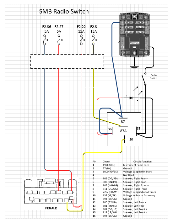
The always on voltage should not be switched, but you could move it to the house battery also. It is generally low power consumption to keep radio memory alive, but depending on radio can also be used as power source when the radio is on.
-greg
|

|
|
|
09-28-2020, 12:34 AM
|
#3
|
|
Senior Member
Join Date: Dec 2016
Location: Southern California
Posts: 108
|
I made a mistake in my initial post. I have 5 speakers, not 6 (edited). The head unit I replaced was a Kenwood CD player and not the stock radio, so someone had been in there before. The adapter harness' connection for an amp leads to a blank on the stock Ford harness. This leads me to believe the van does NOT have a stock amp, but I could be wrong.
I ended up not re-connecting the vehicle's battery to the new radio. I simply wired it only to the house battery system by running a positive wire over to the head unit from my 12v fuse box. Initially I thought I would power both the radio's ignition and battery wire from this one wire and turn the radio off by holding the power button. However, it turns out that the radio doesn't fully turn off when powered down that way, continuing to consume about 2.5W. I added a rocker switch to the ignition wire on the head unit harness, which fully shuts it off (can't detect any power draw on my battery meter). I'm hoping current can't leak from the vehicle battery to the house batteries when wired this way. The only way it would be able to do so would be through the dimmer wire which still connects to the vehicle harness and senses voltage to dim the radio. I have a "battery isolator" in the engine bay but I think this only isolates the power wire coming from the alternator to the house batteries.
New questions:
The speakers are still starting to pop when turning the volume up. They almost get as loud as I would want but not quite. Initially I thought I just need an amp to go louder, but then I noticed the whole audio system isn't using much power. The power draw is about 25W max, with the head unit being about 7W of that! I thought each speaker could get up to 50W (18W RMS) from the head unit. How is the whole system drawing such little power? The speakers have already been replaced. The fronts are Pioneer TS-6874R (4 ohm, 350W max, 40W RMS), side / rear are Diamond Audio D172i (4ohm, 100W max, 50W RMS). Any idea what could be going on? Are the speakers too powerful for use without an amp? Would an 18W RMS speaker sound louder than a 50W RMS speaker driven at 18W RMS (current max of head unit)?
How is the fifth speaker powered? If it's just piggy backed off of one of the rear channels, does the power (and volume) split in order to power it? I noticed with each rear speaker I disconnect I can go slightly louder overall before the speakers start popping.
__________________
Full time vanlifer in my SMB.
@man.and.van on Instagram.
|
|
|
|
|
09-28-2020, 04:54 AM
|
#4
|
|
Senior Member
Join Date: Apr 2012
Location: Philadelphia, PA
Posts: 4,208
|
Installing Alpine stereo into 1992 E250 wired off house batteries
The center and rear van speakers are wired together (in parallel), and many SMBs omit one of the center speakers (often behind a cabinet), leaving only three speakers on that circuit. This setup messes up the ohm draw even more. Ford OEM head units accommodate for this, but aftermarket units dont. Ive installed a few aftermarket units in these setups and they always distort at high volume. On my 98 SMB I added an on/off switch to the speaker in the 60 barn door to be able to turn it off, which solves the problem. I didnt want to totally disconnect it, as we have a third seat back there and my son can hear better when the speaker is on.
A lot more info at this thread: https://www.sportsmobileforum.com/fo...ker-12093.html
|
|
|
|
|
09-28-2020, 08:04 AM
|
#5
|
|
Senior Member
Join Date: Jan 2011
Location: Reynoldsburg, Ohio
Posts: 3,774
|
Is this same issue posted on FTE's Van sub-forum?
|
|
|
|
|
09-28-2020, 12:48 PM
|
#6
|
|
Senior Member
Join Date: Dec 2016
Location: Southern California
Posts: 108
|
Quote:
Originally Posted by BrianW

The center and rear van speakers are wired together (in parallel), and many SMBs omit one of the center speakers (often behind a cabinet), leaving only three speakers on that circuit. This setup messes up the ohm draw even more. Ford OEM head units accommodate for this, but aftermarket units dont. Ive installed a few aftermarket units in these setups and they always distort at high volume. On my 98 SMB I added an on/off switch to the speaker in the 60 barn door to be able to turn it off, which solves the problem. I didnt want to totally disconnect it, as we have a third seat back there and my son can hear better when the speaker is on.
A lot more info at this thread: https://www.sportsmobileforum.com/fo...ker-12093.html |
Cool, that gives me some more info. Yea the center speaker on mine seems to be wired in with the rear right speaker (based on balance/fade testing). The Ford wiring harness does not have a fifth set of wires for the extra speaker and as you say Sportsmobile just wired the extra speaker in parallel with one of the rears. This would indeed mess up the resistance for that channel. However, disconnecting the right rear speaker only slightly improves the situation. The more rear rear speakers I disconnect, the louder I can go without clipping, which again points to the underpowered amp. I haven't tried disconnecting the middle center speaker yet, but if it's wired in parallel with RR, disconnecting either should return the setup to a normal 4 channel 4ohm setup?
I'm still confused as to why the speakers are only pulling 25W max by the time it starts clipping (tested with 40hz sine wave). With 4 speakers connected I would expect at least 15W x 4 = 60W.
Quote:
Originally Posted by JWA
Is this same issue posted on FTE's Van sub-forum?
|
Yes, sorry for the double post, just want to get everyone's opinion.
__________________
Full time vanlifer in my SMB.
@man.and.van on Instagram.
|
|
|
|
|
09-28-2020, 03:31 PM
|
#7
|
|
Senior Member
Join Date: Dec 2016
Location: Southern California
Posts: 108
|
Another clue that is very likely related:
Rear fade & left balance: only rear left speaker plays.
Rear fade & right balance: only rear right speaker(s) play(s).
Front fade & right balance: only front right speaker plays.
Front fade & left balance: ALL SPEAKERS PLAY at full volume (although only the left channel of the track is played)!
Not only do they all play when they shouldn't, but they can go up to a much much higher volume without any amp clipping (some speaker distortion does begin). This is what I was expecting at no fade, no balance. So this is definitely the root of the problem.
This prompted me to check my wiring. The soldering I did from the head unit harness to the speaker wire adapter is correct. However now I'm not sure this adapter harness is correct in the pins that it connects to the vehicle harness. Here are my Ford harness colors (as currently connected through adapter harness):
Right rear - = grey / orange
Right rear += pink / yellow
Right front - = orange / black
Right front + = white / green
Left rear - = red / black
Left rear + = beige
Left front - = black / white
Left front + = orange / green
These do not match up with what I've found online (or what was posted above).
EDIT: I have found a wiring diagram that seems to be more accurate to the colors I'm seeing. It looks like the negative/ground is shared between all speakers. Definitely not how mine is wired!


__________________
Full time vanlifer in my SMB.
@man.and.van on Instagram.
|
|
|
|
|
09-29-2020, 04:00 PM
|
#8
|
|
Senior Member
Join Date: Dec 2016
Location: Southern California
Posts: 108
|
I was up late last night trying to figure out how to wire this thing. I tried wiring in all the negatives into the one common ground from the Ford harness and I felt the Alpine heatsink get really hot, not to mention the more negatives I added the lower the volume I could crank it to before clipping began (very low volume with all of them connected). I did some searching and came across a YouTube video explaining how older cars had a common speaker ground, and that you need a " floating ground adapter" (FGA) to hook up a modern head unit properly. It looks like Ford may have ran this old system up until 1995 or so. The previous owner basically had it wired with just the FL channel being properly grounded. The rest of the speakers were grounded through the fact that they all use the same ground wire. This explains the weird balance, the playing through all speakers when it shouldn't be, the low volume before clipping, etc. It now gets at least twice as loud, without any clipping before speaker distortion (which I don't quite understand since the built in amp should still be underpowered for the speakers).
Here's a picture of the finished harness:

There's battery power coming into the yellow wire, a switch to the red "ignition" wire. The rest of the head unit's harness is connected to one Ford harness adapter that provides the ground and dimmer wire. The speaker wires all go into the FGA, out of which 4 positive and 1 ground speaker wire come out that then connect to the second Ford harness adapter (out of which I took out the other useless pins). The FGA also has a ground on the input side you have to connect to the chassis of the head unit. I soldered the FGA to the Ford harness adapter since this should never need to be removed, but used crimp on terminal connectors for the rest in case the receiver is changed out at some point in the future.

Now I have to cut a hole into the dash with a Dremel for the new switch!
__________________
Full time vanlifer in my SMB.
@man.and.van on Instagram.
|
|
|
|
|
 Posting Rules
|
You may not post new threads
You may not post replies
You may not post attachments
You may not edit your posts
HTML code is Off
|
|
|
|
 » Recent Threads
 |
|
|
|
|
|
|
|
|
|
|
|
|
|
|
|
|
|
|
|
|
|
|
|
|
|
|
|
|
|
|
|
|
|


 Linear Mode