I started this post with thinking about fusing requirements for solar in our vans. As these systems have proliferated on camper vans, there has been some changes in NEC fusing requirements. My intent was to just update those requirements. Some of these fusing requirements are different for series versus parallel, so I thought it would be a good time to go over series versus parallel connections. Then I figured I might as well just start at the controller. Be aware that this post is tedious and has a lot of calculations that I was trying to show. I expect they are correct, but it could be possible I messed up, so don’t be shy, call it out.
What kind of controller, PWM or MPPT
A few years ago, it was evenly split on the use of PWM versus MPPT controllers. MPPT’s were more expensive than PWM’s and you really needed to have some voltage headroom to take advantage of what they offered. As the operating voltage of panels went up, MPPT’s pretty much made more sense. If we look at the same panel with the two different controllers, you can get an idea.
If we use a 100-watt panel that has an operating voltage (Isc) of 18.0V and an operating current (Imp) of 5.56A. This gives you 18 * 5.56 = 100.08 watts. If we take that panel with a PWM or Pulse Width Modulation controller, we get the output voltage or Bat voltage of 14.4V * the operating current of 5.56A = 80.064 watts. Simple put the PWM controller takes the incoming solar current and manages the output voltage or Bat Voltage by changing the duty cycle.
Taking an MPPT or Multi Point Power Tracking controller we the same 100.08 watts out of the panel, the difference now is that MPPT is a DC-to-DC converter that of uses all that power, so your 100.08 watts panel output is converted to 100 watts at the required bat voltage. We get 100 / 14.4V or 6.95A. You have some minor power loses doing the conversion. I like to look at it this way, we get the same 14.4V * 5.56 amps that the PWM controller puts out. The MPPT cam harvest the 18V (Isc) – 14.4 (Vbat) or 3.6 volts * 5.56 (Imp) = 20.016W. 20W/(Vbat)14.4V = 1.39A. Are MPPT controller can put out 14.4 at 5.56A +1.39A or 14.4 at 6.95A.

Certainly, if we were to look at this, we would say that the MPPT controller is a no brainer and worth the cost. The problem is the panel output is based on laboratory results. Specifically, STC or Standard Test Conditions which for the solar ratings is Cell temperature: 25°C, Irradiance: 1000 W/m², Air mass: 1.5. The cell temperature of 25°C would be relatively low for summer usage. The voltage output changes with the temperature enough that they will produce a temperature coefficient. This panel has a (Pmax) coefficient of -0.37% / °C. There are also coefficients for (Vmp), (Vcc), (Imp), and (Isc) The output voltage of the panel drops as temperatures increase. If we were seeing cell temperatures of 50°C (122°F) we would see a reduced Pmax output of 90.75W. The effect of temperature on (Imp) is not much at all, so using the (Imp) we get 90.75 /5.56 = 16.32V. At 16.32 V the headroom isn’t that high, so the difference between PWM and MPPT is not that much. One of the things to note is that Vmp has been increasing, we are now seeing 12-volt panels with a Vmp of 20 volts, and we are seeing larger grid tie panels with a Vmp in the high thirties. Panels with higher Vmp can only be used by MPPT controllers. So, if you have an older low voltage panel, upgrading to an MPPT controller is probably not going to give you the results your hoping for. If you’re going with a new system, MPPT’s will give you more options.
It should be noted that all MPPT’s are not the same, one major difference is the Maximum PV open circuit voltage specification. This brings us to the next topic.
Series or Parallel
Putting solar panels in parallel or series is pretty much the same as putting batteries in parallel or series. If we put the panels in parallel, we keep the voltage and double the current output. The two 100-watt panels would be 18V x (5.56A + 5.56A) = 200.16W. If we put the same panels in series, we would get 36V x 5.56A = 200.16W. Obviously we could not use a PWM controller with those panels in series. That sounds like it might be beneficial, why not that direction. Well, a few years ago, as MPPT controllers were catching on, the smaller MPPT controllers had limited voltage input. One of my favorite Dual DC to DC MPPT controller pretty much suffers from this fate. The voltage input range is limited to around 45 volts.

If we compensate panel voltage for temperature, let’s use 4°F to -4°F then we multiply the above 36 volts by 1.18 = 42.48 volts
There were also concerns about shading on panels, and the going trend was that panels in parallel survived shading better. Now days that is a debatable notion, in part as many cells have bypass diodes at the cell level, versus the row level. This means shading a couple of cells has a more limited effect on the output of the panel. We also look at cost, may times connecting in series means that we take the negative output of one panel and plug it into the positive panel in line. And while our voltage will add up, the current will stay the same (mostly). This means we don’t need any other parallel combiners or bump ourselves up to a higher current carrying wire because out current is increasing as it would in a parallel configuration. It is also possible that we will need additional fusing requirements that we don’t need in series.
To get an idea on how this works we’ll look at a couple of different panels, and of course we should be looking at a few key terms or specifications for the panel. These many times are on a label on the back of the panel.
- (Pmax) – this is simple it is maximum power of the panel, if your purchasing a 100 watt panel that is generally the Pmax
- (Voc) – Open Circuit voltage. This is the voltage you would read when the panel is in the sun disconnected from a controller. This is the voltage you use when you start to put panels in series.
- (Vmp)- Maximum Power Voltage. Some may refer to as optimal operating voltage. This is with the panel connected in a circuit. This is also the number you use when calculating the watts of the panel.
- (Imp)- Maximum Power Current. Again, some may refer to it is optimal operating current. This is with the panel in a circuit. This is the number you use when calculating the watts of a panel.
- The formula for the panel wattage is (Pmax) = (Vmp) * (Imp)
- A couple of other specs or terms needed when putting your system together.
- (Isc) Short circuit current. This would be the maximum current the panel can put out; we use this latter on when determining fusing options.
- Maximum series fuse ratings – this is also used when determining fuse ratings.
- Maximum System Voltage – this is used when putting panels in series.
The important thing to not is that the output of the solar panel is made up of two variables. Voltage of (Vmp) and Current (Imp). The first is voltage, Voltage of the panel is of course derived from the voltage of cells. It should also be noted that the output voltage is effected by temperature. On a hot sunny day the panel voltage will drop, and thus so will your output. One will find that the current is dependent on available light, thus time of day, overcast skies, shading will have a big effect.
Victron probably has put out them most extensive line of solar controllers, so I have identified a controller that will meets the requirements of that PV-Array They will be identified by two characteristics: Voltage level, and Battery Charge Current. Thus, a Smartsolar MPPT 100|20 controller will handle 100 Volt input and supply a max 20-amp charger to the battery. We look for the (Voc) of the panel or panels and multiply by the temperature compensation chart. For the following examples I will use the worst-case compensation temperature setting or multiply by 1.25. To get the battery charge current we take (Pmax) of the panel or panels and divide by the Vbat setting. Vbat will the absorption level that the charge controller is set for. For the following examples I will use the value of 14.4V for Vbat. Victron controllers are pretty known for needing 5V above Vbat to turn on, this is on (Voc). While I have seen some controllers Morningstar come to mind that only need a volt over Vbat. In many ways this makes sense, as it’s clear that Victron Controllers are designed for panels in series.
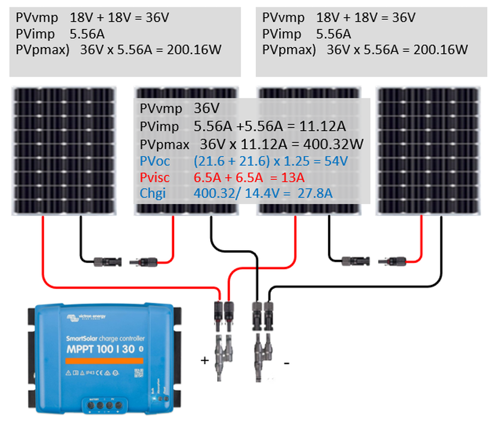
Now that we have some of the terms down let’s look at them in use. We can use these three panels as our examples. The first one will be a 100-watt panel the HSP100D-L from HQST

So for this 100 watt panel, we can install it in series or parallel, or for that matter series/parallel if we have enough panels.

You will notice that both series and parallel give you the same output at the STC rate. The predication of most MPPT controllers is to see a + 5 volt above battery charge voltage to turn on. So if the Bulk or absorption is 14.4 V, your start up voltage would 14.4 + 5 or 19.4 Volts. The good news is that is based on (Voc) of 21.6V The other spec of the controller is the PV short circuit rating, this is rated at 15A, which covers the PVisc in both configurations. I show both of these set ups will work with Victron SmartSolar MPPT 75|15. For the parallel configurationsI show some standard MC4 combiners.

Again in parallel we add the current or (imp) together, in series we add the voltage of (Vmp) together. In the parralel case if we have a 15 amp controller this would be to high for that controllers. And while we don’t show it in the picture the (Voc) is also being added in parallel. So the (Voc) 21.6V + 21.6+21.6 = 64.8V. We would need to adjust that for expected worst case cold temperature and we would need a controller with a PV voltage input of over 81 Volts. The Victron 100|20 is just a little low on the Charge Current. The unit would cut off at 20 amp charge. If you want more room then you could move to the 100|30.
Now let’s look at 4 panels. As we can see the four panels in series pushes our voltage above the limits of the 100|30 and we need to move up to the 150|35. On the parallel side our current is running over 20 amps, we need to start managing our voltage lose due to wire size.

To round out the look I configure the four panels in a Series/Parallel configuration. This will give us the advantage of getting a higher (Vmp) , but we can keep the PV input voltage below ((Voc) 21.6 + (Voc) 21.6) X 1.25 (worst case cold temp correction) = 54V . The current is also more manageable.
The next two panels will be an example of why you need to pay attention to the details. Both of these panels are sold by Rich Solar, and both are listed as 200 watt panels, they both have the same physical dimensions. That is where the similarities stop the RS-M200 is a 200 watt (12 volt panel), while the RS-M2000 is a 24V panel.

The RS-M200 has some very good specs, A (Vmp) of 20.4 volts and a current (Imp) of 9.8A. This would be a very solid 200 watt panel.

It appears the RS-M2000 is made with half cut cells. This basically increases the number of cells and thus the voltage output of the panel. Another feature of the half cut cell is better built in performance when it comes to shading. In reality this panel looks like two 100 amp panels in serial. If one was looking for a single or dual 200 watt panel set up the RS-M2000 would be my go to panel.
It starts out with a Vmp of 37.6V, this should have plenty of start up voltage, and with a (Imp) of 5.32 the current level is low.

Even though all 4 configurations are putting out 400 watts we have the RS-M2000 in series forcing us to go to a larger controller because of voltage.
In the three panel configurations we see much of the same, in series the RS-M2000 panel is forced to a larger controller because of the series voltage is over 170 volts. But on the other side, when we have three panels of the RS-M200 panels in parallel the current is over 30 amps. The short circuit current Pvisc of 30.6A is higher than the MC4 connector specification of 30A. This will cause us to use a larger and probably more expensive roof combiner.

Then we move on to the landing pad configuration of four 200-watt panels. The 800 watts of panels pretty much drives the size of the controller for all configurations. As in the three panel RS-M200 config the current is too high for a MC4 combiner, we need to move to a combiner box. The higher array open circuit current on the series configuration of the RS-M2000 forces us to the larger MPPT250|60 controller.
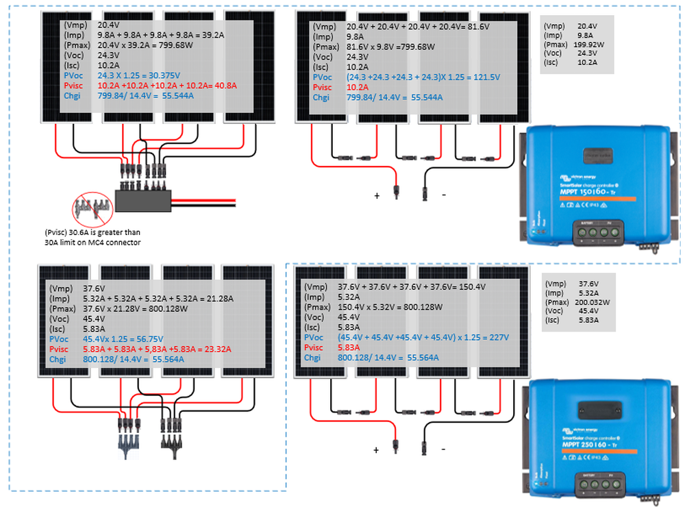
The 800 watts of panels pretty much drives the larger controller for all configurations. As in the three panel RS-M200 config the current is too high for a MC4 combiner, we need to move to a combiner box.
Again, in the below diagram we see the series/parallel approach. This will take our configuration of RS-M2000 panels back to a slightly smaller (read cheaper) controller. The serial/parallel approach can work out really great, but generally you need 4 identical panels.

Now that we have seen the possible layout considerations, which is better serial or parallel? I laid out the different configurations to help aid the benefits of one or the other. Putting the panels in series is generally considered cheaper, due to smaller wire size, no added cost of solar combiners and fusing. To be clear we have seen where the cost of the controller may go up as we have to meet the higher voltage of some configurations.
The big problem with panels on top of the van is shading. For those of you that don’t camp in the shade, this may not be a priority, but for those that do, the impact may be high. As we have seen when in series, we add up the voltage and keep the current of all the panels the same. If we have a panel that is impacted by shade it will reduce the current of that panel. The voltage is not that impacted by shade. So now if we have a panel that might be putting out 50% as much in current as the other panels in the series string. When we look at the numbers, we now see that all the panels are impacted by 50%

The effects of shading are real, and depending on your camping preferences it might be something to look at. Why then do you see such a big presence on the web talking about series configuration. The consensus is that the voltage will be high enough to start the charger earlier then you would get when in parallel. And that does make some sense, you can see that we were very close to the turn on voltage of the 100-watt panel, we were close in the RS-M200 panel. The higher Voc panels would appear to negate that advantage.
Mismatched panels
If you have stuck with me this far you might be wondering about mismatched panels, you can see that the effects of voltage and current on a string of panels. Many times, people will decide to add another panel to an existing panel, so again what are the effects of mismatched panels. For this comparison I picked a panel that is a few years old. While it is very similar to the RS-M200 in physical size, it is 180 watts to the 200 watts. If we look at the specs, we see that the cells have become a bit more efficient, so we see a slight rise in voltage 20.4V to 19.67V and a slight increase in current 9.8A to 9.15A to get that increase of 20 watts (180W to 200W).
Now, one thing we didn’t see when doing are other series parallel comparisons was the effect of different voltage, we just added the currents in parallel. Well, in series, when we have a panel (Vmp) difference, it is like current and effects the remaining panels.

When we look at the two panels in Series, we get the lower (Vmp) of 19.67 and we add the current (Imp) together 9.15A + 9.8A = 18.95A. This gives us a (Pmax) 19.67V x 18.95A = 372.75W out of 380W or 98%
When we look at the two panels in parallel, we get to add the voltages together (19.67 + 20.4V), of course the current (imp) is the lower of the two panels. This gives us a (Pmax) 40.7V x 9.15V = 366.64W. This would 366.64W out of 380W or 96.5%. In either configuration the mismatched panels aren’t huge in this case.
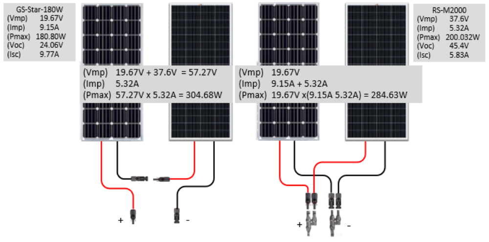
If we are to compare the GS-Star-180W panel with the newer RS-M2000 panel, there is a big difference. In this case in series is the better of the two. Of course, we add the (Vmp) together 19.67V + 37.6V = 57.27V. We take the lower current of two panels 5.32A and come up with 304.68W. If we look at parallel the (Vmp will hold at the lower of the two panels 19.67V, but we do get a boost in current (9.15A + 5.32A) which comes out 284.63 watts. Putting these two panels together will give you an increase but at a high price.
Sometimes we can use Series/Parallel to aid in getting the best result out of mismatched panels.

In this example we again use two older GS-Star-180W panels and the RS -M2000 200-watt panel. The GS-star-180’s have a (Vmp) of 19.67 volts and (Imp) of 9.15A). The RS-M2000 has a (Vmp) of 37.6V and (Imp) of 5.32 volts. A quick look and we realize the (Vmp) are two far apart for parallel and the (Imp) are two far apart for serial. But if we put the two GS-Star panels in series, the (Imp) are the same, we end up with a combined (Vmp) of 39.43 and (Imp) of 9.15. Now we pair that group with the RS-M2000 in parallel. The (Vmp) difference will be 39.43 – 37.6 or 1.83V, in parallel the current won’t matter. When we do this Series/Parallel grouping we get a total (Vmp) of 37.6 and a (Imp) of 14.47 for 544.07W. This is 97% of the panels added by themselves.
Now that we have a better understanding of parallel and series or a combination, the effects of shading, mismatched panels, we can add one more variable that I find important. That is auxiliary solar panels. I like to be able to deploy auxiliary panels while at the campsite if needed. Now we can see that adding auxiliary panels to an already parallel configuration should be easy, we just need to match the (Vmp) as close as possible to the existing (Vmp) on our permanent panels. Now in series, we would just try to match up the (Imp) as close as possible. The bigger problem becomes wiring in series. With parallel I can just add an aux connection, if a panel is not plugged in, no problem. In series if we had the aux connector, we would need some way to switch around the missing panel, when the portable units were not deployed.
The other way to handle auxiliary panels would be to add a second controller. This is not my preferred method but can be done. You do have to watch out that your solar controllers are in sync if possible. Many larger units have the capability of a master/slave relationship, but if you were adding a cheap controller that came with a portable unit it would not. I would generally have no problem with using both when doing bulk charging, but one we get to absorption, I really only want one controller working. There are various ways to may this work, but a little more complicated than just one controller.
For an example of aux solar I will show my van.

I originally didn’t think putting solar on top would be an issue, but I soon found out the dual vents and air conditioner took up more space then I wanted. I was able to find two Renogy 100 watt compact panels that fit on the sides of the front fan. The back 90 watt unit was narrow and fit between the back of the air conditioner and rear fan. I currently have a relay in place to change the output of this panel to a separate controller dedicated to the Transit Start batteries. Keeping with the general RV panels in parallel mode I also chose these units to keep the (Vmp) voltage as close as possible (17.9V and 18V).
When it came to look for auxiliary panels, I chose two 100W that also came in at 18V. In this case I chose the two 100W panels over a larger panel, as I found it is easier to deploy two of the smaller setups versus a larger one. My auxiliary port has two inputs already wired in parallel, so two is as easy as one. As you can see from the output, the panels match well together with a calculated output of 99%.
The whole series versus parallel thing has got me thinking, I understand the arguments for each case. I made another example of my van if I wired in series.

Looking at my choices of panels, the Zamp 90 watt has a (Imp) of 5A, the other four are 5.6 and 5.58, so I will be losing a half amp from those four panels. The numbers come in at 449W. If I were to have the Zamp wired to the starter, the other four would be close to 400W as they are well matched. And of course, the big question what would I do when the aux panels were not in?
More importantly if you were to already have a 36-volt panels on top of your van, say the RS-M2000, you could wire the two aux in series and have a pretty good match for an aux hook up.

Here you can see the two RS-M2000 have a (Vmp) of 37.6V. By putting the two Lensun 100w panels with a (Vmp) of 18V in series to each other I bring their combined (PVmp) up to 36V. To be fair Lensun also makes some 36V folding panels or blankets.
This configuration would be pushing the limits of my controller.

Here we add a Lunsun Solar Blanket to the mix, bringing my calculated input up to 785W or whopping 54.5 A of charge at my bat charge voltage. As you can see my combined short circuit current is higher than the rating for my Victron 150/60 MPPT controller. A 50-amp breaker will make sure we don’t destroy the controller. This all that brings me to what I started to sit down to discuss.
Fusing and Disconnects.
As with many things it took the NEC a little time to catch up to the solar installations. And RV installations are not their primary focus. In the last couple of years there have been changes to their code. One of the big ones has the inclusion of a disconnect switch between the solar arrays and the controller. A disconnect should disconnect both conductors at the same time. While the disconnect, can be a breaker it does not have to be. The disconnect becomes even more important with higher voltages of a Series PV layout. When looking for a breaker make sure you look for a breaker that can handle the higher voltage. While you can find some dc breakers like A-series , you may find that the highest voltage they support is generally 65V DC. For that reason, I would recommend a breaker rated for solar, as they will rate for 1000V or higher. Another option is a solar combiner box, with a isolator switch. With this switch the amp rating is just for the switch capacity, it is not a breaker so you would need an inline fuse along with the isolator switch.
When it comes to fusing, we look at NEC code 690.9.
Circuits Where Overcurrent Protection Not Required
Overcurrent protective devices shall not be required where both of the following conditions are met:
(1) The conductors have sufficient ampacity for the maximum circuit current.
(2) The currents from all sources do not exceed the maximum overcurrent protective rating specified for the PV module or electronic power converter.
- We need to look at the maximum series fusing of the panel or panels in our array.
- We will need to calculate the maximum current.
- The maximum current shall be the sum of the short-circuit current ratings of the PV modules connected in parallel multiplied by 1.25.
- We also need to look at the Solar Controller datasheet for Maximum PV short circuit current.
So serial can be pretty easy, we check our largest short circuit current (if mismatched) X 1.25 As long as this is lower than the ampacity of our wire, lower than our maximum series fusing, and also lower than the solar controller Maximum PV short circuit current; no fusing would be required. If your controller does not specify a Maximum PV short circuit current, you could fuse using panels series value.
So while you don’t need the fuse, we could default and use a dual breaker as our disconnect. This will insure no possible damage could occur if the controller was bad.
Now Parallel fusing is different, with each panel we have their own current source. The problem arrives if we were to have a problem with one of the panels. If we have a short circuit on a panel, that could provide a path to ground for the remaining panels. For the most part most panels have other features to prevent this, but from a code standpoint it is possible. So number(2) above would tell us that we need to provide additional fusing.
In the diagram below we can that our maximum series fuse rating is 15 amps, no problem the panel only puts out 5.83A. The problem arrives when we have a short circuit in one of the panels. Unfortunately, the short circuit has provided a new path to ground. If we look at the combined current of the remaining panels in the array (5.83A + 5.83A + 5.83A = 17.49A). We can see that that current combined with the 5.83A of the offending panels would be higher than the Maximum Series rating of 15A. Two prevent that the fuse for the offending panel would be to match the maximum series fuse rating, which is 15A. All the parallel panels would have this fuse in place. It is little confusing because the fuse is not for the output of the offending panel, but instead to protect the input form the remaining panels.

If we look at three panels in parallel, we find a similar setup. Again, the remaining two panels have a short circuit of 11.66A. That is not over the 15A maximum series fuse rating, but if combined with the current in the bad panel it could be 17.49A and exceed the 15A maximum series fuse rating. In this case if we relied on matching the 15 amp fuse rating it would not do any good. The 10-amp fuse should protect the shorted panel and still be high enough not to provide false current trips.

Now we get to a situation where we technically meet the requirements of fusing, but we will find it is useless in application. The combined short circuit current of both panels (20.4A) is greater than the maximum series fuse rating of 20A. The problem arrives we can add the 20 amp fuse to each panel, but the value will be too high to prevent the current from the remaining panel. If we drop the fuse to 10-amps it will be to close to the panel Imp current of 9.8A and cause false trips. So the fuse will add no value but technically should be included.

-greg


 AWOL
AWOL 2008 GMC 3500 SMB

 Linear Mode