|
|
 10-02-2017, 08:40 AM
|
#21
|
|
Senior Member
Join Date: May 2014
Location: OrangeCounty, CA
Posts: 1,275
|
Greg, thanks for this!
My rig is a 1995.
(It's lived its whole life on the West Coast though, for what it's worth --- so it's pretty rust-free. The battery terminals (and entire under-hood area/components/wiring/connections) all look pretty darn good. I made a point of sanding the starter battery's terminals *extra clean* yesterday while I had the cables disconnected.)
Two questions, if I may:
1) what was it in particular (in what I already posted) that makes you feel conclusively that my isolator is bad? It does seem to still be "isolating," and has approximately a 0.7 volt diode drop, I'm curious what is standing out to you as a telltale indicator of something amiss?
And
2) I'm not sure if my multimeter has a diode check -- is this function necessary for the test you just showed/described? (It seems so.)
For what it's worth --- although I didn't mention it or show it, after I checked for continuity across terminals 1 and 2, I *also* checked for continuity across all possible other combinations of terminals on the isolator....and found there was no continuity to be found across any of them, in any combination.
But that was of course just a standard, basic continuity check, not a "diode check" as you are indicating....and when my test meter showed "zero continuity," I didn't think to swap the test-probe terminals to reverse the polarity of the testing. Hmmmm....
I'm guessing that a "diode check" applies a larger, known current/voltage via the test meter simultaneously as it checks for continuity. Is this correct?
Again thanks Greg! 
__________________
Mike T
___________________
'95 Ford E250 RB30 PH
|

|

|
|
10-02-2017, 08:48 AM
|
#22
|
|
Senior Member
Join Date: May 2014
Location: OrangeCounty, CA
Posts: 1,275
|
Quote:
Originally Posted by DCHitt

Your alternator regulator seems to be sensing the chassis battery at the battery. You might see an additional wire (smaller size) on the plus chassis battery terminal.
That would make the alternator track to the chassis battery rather than the alternator output.
That would be a correct implementation for a seporator.
|
Thanks for this DCHitt!
There is indeed a "split terminal" at the positive connection for the starter/chassis battery. Two, equal-sized positive cables run off to parts unknown under the cowl.
At the house battery there are *also* two positive leads attached.
From other sources that I am reading now, it appears that it is actually pretty standard practice in isolator installations to do some sort of "voltage sensing at the battery" in order to prompt the voltage regulator/alternator to kick out sufficient additional voltage --- and thus overcome/compensate for the isolator's diode-based voltage drop.
Without this compensation, it seems that neither the chassis or house battery would see enough voltage to recharge in a reasonable amount of time (or even keep up with the under-hood electrical needs to run the vehicle.)
__________________
Mike T
___________________
'95 Ford E250 RB30 PH
|
|
|
|
|
10-02-2017, 10:01 AM
|
#23
|
|
Senior Member
Join Date: May 2007
Location: Beaverton, OR
Posts: 2,506
|
Quote:
Originally Posted by MountainBikeRoamer
Greg, thanks for this!
Two questions, if I may:
1) what was it in particular (in what I already posted) that makes you feel conclusively that my isolator is bad? It does seem to still be "isolating," and has approximately a 0.7 volt diode drop, I'm curious what is standing out to you as a telltale indicator of something amiss?
|
The fact that removing the isolator and hard wiring the alternator and batteries back in parallel and the alternator provided reasonable output voltages. So the voltage regulator of the alternator appears to be working.
With it in, the voltage regulator appears to operate like it is noy getting feedback, and thus going high
Quote:
|
2) I'm not sure if my multimeter has a diode check -- is this function necessary for the test you just showed/described? (It seems so.)
|
Yes, I believe if you are using a digital multimeter, you need to use the diode scale.
-greg
__________________
-greg
__________________________________________________ ______________
"Goldilocks" 2020 Ford Transit High Roof Extended 3.5 EcoBoost AWD Homebuilt
|
|
|
|
|
10-02-2017, 11:13 AM
|
#24
|
|
Senior Member
Join Date: May 2014
Location: OrangeCounty, CA
Posts: 1,275
|
Quote:
Originally Posted by Scalf77
The fact that removing the isolator and hard wiring the alternator and batteries back in parallel and the alternator provided reasonable output voltages. So the voltage regulator of the alternator appears to be working.
With it in, the voltage regulator appears to operate like it is noy getting feedback, and thus going high
Yes, I believe if you are using a digital multimeter, you need to use the diode scale.
-greg
|
Ok, thanks again Greg! I think I follow you....
..... but shouldn't the voltage regulator be doing exactly what it's doing? And the isolator as well?
It seems to me that the voltage regulator is getting feedback (it's measuring supplied voltage at the battery terminals somehow using that second positive wire?) and it's because of that feedback that it is "compensating" and raising voltage to overcome the isolator's 0.7 volt diode drop....?
Otherwise --- if I understand you correctly ---- if the voltage regulator didn't react whatsoever to the voltage drop at the isolator....
.... then I'd only be seeing 14.38 volts at the "A" terminal of the isolator , (instead of the measured 15.13 volts when the isolator is part of the circuit) ---- and then the "output" of each of the other two terminals 1 and 2, running off to the chassis/starter and house batteries, would only be:
[~14.38 volts alternator input] - [ 0.7 volt diode drop ] = 13.68 volts
Which seems (to me) to be too low to do a sufficient job of charging the batteries. From what I read, you want to see between 14.2 and 14.7 volts supplied at the starter/chassis battery terminals to properly charge the battery (and keep up with the electrical demands of the vehicle when it is operating.)
Clearly I'm missing something.....but what am I missing?
Thanks good sir!
__________________
Mike T
___________________
'95 Ford E250 RB30 PH
|
|
|
|
|
10-02-2017, 12:08 PM
|
#25
|
|
Senior Member
Join Date: Mar 2015
Posts: 121
|
Quote:
Originally Posted by Scalf77
It looks like your isolator is bad, I expect the .2 volt drop is caused by a bad l connection, corroded cable or terminal connection. What year is your rig?
Here are the basic checks I usually do on an isolator. I took these pictures while working on a members van a couple of moths ago.
First I check from Terminal A (alternator) to Terminal 1 (chassis battery), if your meter has diode check, you can use it. You need to check in both directions, because of the diodes. You can see that reading changes based on the polarity of the probes.
The first pictures shows the current is flowing through the diode.

Reversing the leads we see that the diode is blocking the current in that direction.

Now we move to Terminal A (alternator) to terminal 2 (house battery) and again do the same checks.
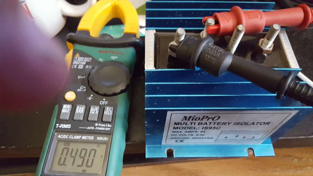

Now I check out Terminal A (alternator) to the Terminal E (excite) and provide the same checks


And the check of course that you already did, between terminal 1(chassis) and terminal 2 (house). Again I usually do this in both directions (i only have a picture showing this in one direction. Actually, this is usually the first check

hope this helps |
Hi Greg,
I have a question, and I apologize for it being a stupid one...BUT - is the isolator shown in these images a good isolator, or a faulty one? If I test my own isolator, should I WANT to get readings similar to what you found in these images? Or if I get these numbers, is it time for me to replace my isolator?
thanks,
capn
|
|
|
|
|
10-02-2017, 02:33 PM
|
#26
|
|
Senior Member
Join Date: Apr 2014
Location: Poughkeepsie, New York
Posts: 122
|
Quote:
Originally Posted by MountainBikeRoamer
From other sources that I am reading now, it appears that it is actually pretty standard practice in isolator installations to do some sort of "voltage sensing at the battery" in order to prompt the voltage regulator/alternator to kick out sufficient additional voltage --- and thus overcome/compensate for the isolator's diode-based voltage drop.
|
Yes, it is necessary to sense at the battery but it is only necessary to sense one side because it is assumed that the diode drop will be the same on both sides no mater how much the current is different on the two sides.
The battery that needs to be charged should hog the current while the voltage will be the same on both sides.
You may still have some bad batteries, connections, diodes, or wire drops that can make measurements differ. The trick is to understand how it works so the meter tells you something useful.
__________________
2015 Promaster Sportsmobile
KB2ZE
Old retired IBM Engineer
|
|
|
|
|
10-02-2017, 03:54 PM
|
#27
|
|
Senior Member
Join Date: Aug 2016
Location: Reno, NV
Posts: 1,420
|
Get yourself a Blue Sea 7622 and win.
__________________
<br>
Tim - 2013 EB V10 Agile 4x4 SMB PH Ginger Army All Terrain Mobile HQ
|
|
|
|
|
10-02-2017, 04:29 PM
|
#28
|
|
Senior Member
Join Date: May 2014
Location: OrangeCounty, CA
Posts: 1,275
|
Quote:
Originally Posted by Flux
Get yourself a Blue Sea 7622 and win.
|
Haha!
I'm definitely intrigued with the Blue Sea separators, and there's a good chance I'll eventually have one in place of a traditional (old-school) diode isolator.
But until its clear why my current overall charging loop/battery setup is doing weird things, I'm not going to head off in the direction of preemptively swapping out components. (Especially since the isolator might not be the culprit here.*
(*True enough, it may well indeed be the isolator, but insofar as what I've gathered, the testing data I've logged thus far is not enough to confirm or rule out malfunction in it. I need to test for diode flow-through in both positive and negative directions.)
That said --- if this isolator is indeed kaput --- I may likely just get another, brand-new and identical one from Sure Power. They're only $50, and its an easy replace, and I know it worked before. I'm a keep-it-simple kinda guy, if I can be. And I'll be honest --- I'm still not sold on the benefits of the Blue Sea separators, perhaps I'm still just not grasping what is so much more awesome about them. Maybe I'm not a sophisticated enough electrical guy, or perhaps my van's basic house electrical system is just so simple as to not create the glaring need.
Sure, separators don't have the 0.7 volt diode drop across them....but as my testing has indicated (and DCHitt's information has validated), proper installation of an isolator takes into account the potential for diode voltage loss, and incorporates at-the-battery sensing of final delivered voltage.... ensuring that the alternator/regulator still deliver the correct charging numbers to the batteries. So to the batteries --- it all looks the same, isolator or separator. They still get the required 14.2 - 14.7 volts they need to charge.
True, perhaps an isolator creates a bit more load on the alternator over time to do so, but does this impact observed operation in the real world? I certainly haven't seen that. At least not in terms of needing to replace the alternator. (I don't think so anyway, haha....I've done most of the alternator testing from the video Tomsbeast posted, but I admittedly haven't fully tested every aspect yet, lol.....)
That said -- something is indeed causing the chassis/starter battery to run down and fail, and I should perhaps allow for the possibility that this charging system is perhaps far from perfect in its original "state-of-the-art.....as envisioned 20 years ago" configuration. I do honestly hope to eventually become enlightened as to how a separator could potentially be part of making a significant difference/improvement in this respect. (Really, truly!)
__________________
Mike T
___________________
'95 Ford E250 RB30 PH
|
|
|
|
|
10-02-2017, 07:24 PM
|
#29
|
|
Senior Member
Join Date: Apr 2014
Location: Poughkeepsie, New York
Posts: 122
|
Quote:
Originally Posted by Flux
Get yourself a Blue Sea 7622 and win.
|
One advantage that a separator has is that it can be used to jump start the chassis battery using the house battery. That could help.....
__________________
2015 Promaster Sportsmobile
KB2ZE
Old retired IBM Engineer
|
|
|
|
|
10-02-2017, 07:30 PM
|
#30
|
|
Senior Member
Join Date: Aug 2016
Location: Reno, NV
Posts: 1,420
|
Yep. My only issue is that I put 150 amp terminal fuses. So I would have to combine and hang out for a bit, then crank.
__________________
<br>
Tim - 2013 EB V10 Agile 4x4 SMB PH Ginger Army All Terrain Mobile HQ
|
|
|
|
|
|
 Posting Rules
|
You may not post new threads
You may not post replies
You may not post attachments
You may not edit your posts
HTML code is Off
|
|
|
|
 » Recent Threads
 |
|
|
|
|
|
|
|
|
|
|
|
|
|
|
|
|
|
|
|
|
|
|
|
|
|
|
|
|
|
|
|
|
|


 Thirsty
 Dusty
Dusty Linear Mode