Journey with Confidence RV GPS App RV Trip Planner RV LIFE Campground Reviews RV Maintenance Take a Speed Test Free 7 Day Trial ×


Reply
 
Thread Tools Display Modes
 
Old 05-27-2023, 01:51 PM   #1
Junior Member
 
Join Date: Feb 2022
Location: Graeagle, CA
Posts: 22
2002 E350 Leader Ambulance Camper Build wiring questions.

Greetings all.
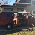
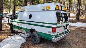
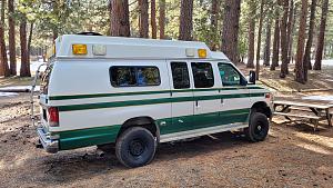
My wife and I picked up this 2002 E350 Ambulance from a hospital I worked at last year. It has 168,000 miles and they added a 4WD package.
We used it as a tow vehicle for our Airstream and now I'm in the process of converting it into a camper.
I've poured thru the threads related to this conversion but still have a few "Leader specific" wiring questions.

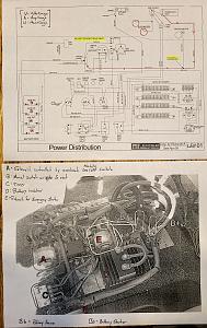
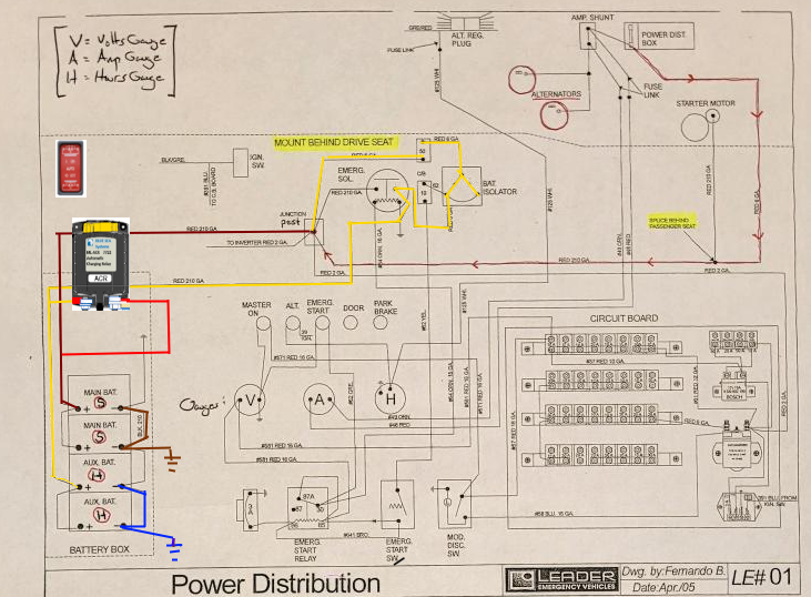
Here is a picture of the Power Distribution mess under the front seat. (photo from Boltline) along with the schematic that Leader sent me.

Here are my aspirations:
1. I'd like to remove the timer (C.)

2. I want the dual alternators to charge both banks of batteries (2 starter and 2 house). From what I understand in the schematic, the starter batteries are charged via the alternators and the house batteries are connected to the Emergency Solenoid and don't receive a supply from the alternators unless its activated. This solenoid is connected to a switch which lets you start the van with the house batteries if the starter batteries are dead.
Is it as easy as splicing into the alternator output and installing a battery isolator for the house batteries?
It looks like there's a splice under the passenger seat I could use (highlighted).

Click image for larger version

Name:	ambowiring.jpg
Views:	27
Size:	183.3 KB
ID:	47290

3. There is a Vanner inverter under the rear cabinets which I'm still learning about. Am I right in thinking that when connected to shore power its this inverter that is charging the house batteries as well as supplying 110 to the interior outlets?

20-1050CUL.pdf

Thanks for any help with this.

Click image for larger version

Name:	amboex2.jpg
Views:	3
Size:	188.0 KB
ID:	47291

Click image for larger version

Name:	amboex1.jpg
Views:	3
Size:	208.0 KB
ID:	47292

Click image for larger version

Name:	ambointer.jpg
Views:	1
Size:	181.0 KB
ID:	47293


Thanks for any help you can offer!

Ambolorian is offline   Reply With Quote
Old 05-28-2023, 10:55 AM   #2
Senior Member
 
Scalf77's Avatar
 
Join Date: May 2007
Location: Beaverton, OR
Posts: 2,504
So it does look like designed, it does actually use a diode isolator ( not as intended) to charge your house batteries. I have outlined the path.


I would replace that hole mess with a BlueSea 7620 or 7622, if it was me. I would have to spend more time to figure out the timer, and what it does.

I would say that the grounding of the batteries is definitely not ideal.

The inverter/charger is a modified sine wave unit, with two charging profiles Flooded and Gel.

-greg
Scalf77 is offline   Reply With Quote
Old 05-28-2023, 11:59 AM   #3
Junior Member
 
Join Date: Feb 2022
Location: Graeagle, CA
Posts: 22
Thanks for the reply Greg.
The first thing I did before posting this was to read your Sticky on the subject. That was very helpful, I appreciate the time it took to make that.

I think I'll heed your advice and go the BlueSea 7620 route. I'll need to pour over this a bit longer to see what I can remove and how to retain the ability to start engine with the house assist when the temps are super low. Would I be able to remove the stock battery isolator/bridged diode and connect both banks to the BlueSea?

As for the grounding comment.. would it be better for each terminal to have a dedicated ground post?

Thanks again.
Ambolorian is offline   Reply With Quote
Old 05-28-2023, 12:39 PM   #4
Senior Member
 
Scalf77's Avatar
 
Join Date: May 2007
Location: Beaverton, OR
Posts: 2,504
It is a little crude update (I'm watching the Indy 500), but this should kind of give you the idea.


When the switch is in auto the batteries will connect based on voltage. The switch on will allow jump start or assist for starting.

The ground change doesn't look like much, but it is about balancing the batteries in parallel.

obviously the other stuff can be removed.

-greg
Scalf77 is offline   Reply With Quote
Old 06-04-2023, 10:47 AM   #5
Senior Member
 
Join Date: Dec 2014
Location: Riverside Ca.
Posts: 740
I'd like to ask some more questions on this subject/post. This may help OP or others with similar questions.I also have a 2002 with 7.3 and Ambo dual alternators. package when I ordered the van in2001. I have yet to check If the second alt. Is hooked to anything since it is a 15 passenger set up. Question 1: I heard you should not hook up lithium and flood batteries together, true or false. I heard that something is to go between.
2 why not just run each alt to each battery bank and if there is that something device, put it between a power cut off switch and the flooded bank for emergency jump start??
3 But.. I also heard these alt are not compatible or need alteration to work with lithium bank??
I am presently wiring house bank and want all options, shore/generator, solar, alternator!
Vanimal is offline   Reply With Quote
Old 06-04-2023, 11:33 AM   #6
Senior Member
 
Scalf77's Avatar
 
Join Date: May 2007
Location: Beaverton, OR
Posts: 2,504
Quote:
Originally Posted by Vanimal View Post
1: I heard you should not hook up lithium and flood batteries together, true or false. I heard that something is to go between.
The generally excepted answer is true, but hooking them together will not be catastrophic issue. One could even say they are some advantages. But with anything, there are some downsides. You can't really adhere to the charging parameters of both different chemistries at the same time. So that means you would be compromising on both. This would generally result in less cycle life than each could get if they were separate.
Quote:
Originally Posted by Vanimal View Post
2 why not just run each alt to each battery bank and if there is that something device, put it between a power cut off switch and the flooded bank for emergency jump start??
There are devices that will let you combine both the lead acid start batteries with house batteries just like you would with to lead acid systems. The difference is they monitor and try to disconnect with out completely charging the lithium battery. Li-BIM. There are also DC to DC chargers that are used between the two battery systems. This just uses power from your Alt/Starter and turns it into a charger that you set for Lithium. Yes, you can jumpstart between the two, depending on what you are using between the two systems, you may have to be creative.

Quote:
Originally Posted by Vanimal View Post
3 But.. I also heard these alt are not compatible or need alteration to work with lithium bank??
If you were to separate your two alternators, you would not want to run one of them directly to a lithium battery. Generally their output is higher with a lithium and exceeds the cooling capacity that one would get with the alternator spinning at those same RPMs. This is generally an issue that shows up at idle. You can put an external regulator on the alternator that will turn it into a dedicated charger for whatever chemistry you want. Balmar and Wakespeed make them. I know for sure the Wakespeed monitors the Alt temp and will throttle back if needed. I haven't looked at the Balmar in a while.

-greg
Scalf77 is offline   Reply With Quote
Old 06-05-2023, 07:44 AM   #7
Senior Member
 
Join Date: Dec 2014
Location: Riverside Ca.
Posts: 740
Thanks for your help. I think I am still lost.
#3 To carify don't run the aux alt directly to Litho's without some sort of regulator that slows or reduces voltage input to Litho bank or it will cook them.
#1 Don't hook them together unless you want to shorten the cycle life of the Litho's.
#2 The monitor of the devices will disconnect with out completely charging the lithium battery.
The DC to DC charger seems to not be the answer because I am sure it's one way charge either lead flood to Litho or Litho to lead flood.
Lastly if it's not good to direct hook up to both banks because of lowered cycling life then would a manual shut off not be the answer.
Vanimal is offline   Reply With Quote
Old 08-04-2023, 11:41 AM   #8
Junior Member
 
Join Date: Feb 2022
Location: Graeagle, CA
Posts: 22
Hi Greg,
I finally have all my supplies: battery cable wiring, heavy duty crimper, Blue Seas 7620 and fuse panel, master switch, fuses, battery monitor, etc.
Here is a my power distribution schematic. Sorry for the mediocre drawing.
I'm hoping with this setup I'll be able to delete the original diode isolator and the Emergency Solenoid and keep each battery bank happy.
Safety is my goal and I was hoping to get your input.

Click image for larger version

Name:	schematic.jpg
Views:	5
Size:	76.9 KB
ID:	47934

Here is the Timer I'm looking to delete as well. Does it make sense to just toggle the far left switch to OFF or do I need to remove the whole contraption?

Click image for larger version

Name:	underseat6.jpg
Views:	7
Size:	145.5 KB
ID:	47933

Thanks!
Ambolorian is offline   Reply With Quote
Old 08-05-2023, 07:38 AM   #9
Senior Member
 
Scalf77's Avatar
 
Join Date: May 2007
Location: Beaverton, OR
Posts: 2,504
So in your drawing you have a wire going from the junction post straight to the house batteries. This creates a direct path from starters to house batteries, making the ACR path somewhat worthless. So remove the wire from junction to house.

Not knowing what it is connected to, I would first try turning off and seeing impact. But, ultimately if your not using it - take it out. It

Battery shunt should be closer to the battery. You should also make a ground bus of some sort. Your ground wires from the batteries should go upstream of shunt (load side) In the way you have it configured the shunt would not record charge from alternator.

What size wire and distances ?
__________________
-greg
__________________________________________________ ______________
"Goldilocks" 2020 Ford Transit High Roof Extended 3.5 EcoBoost AWD Homebuilt
Scalf77 is offline   Reply With Quote
Old 08-05-2023, 11:25 AM   #10
Junior Member
 
Join Date: Feb 2022
Location: Graeagle, CA
Posts: 22
Click image for larger version

Name:	schematic4.jpg
Views:	4
Size:	229.6 KB
ID:	47955


Not sure what compelled me to put that third wire from Junction to House. Thanks for catching that.

As far as gauge and distance: I'm matching what Leader used thru-out for the battery cables, (00) and I'm running everything from the battery box under the driver's side a short distance to behind the driver's seat against the wall.

Thanks for the input Greg, I really appreciate your time and knowledge.
Ambolorian is offline   Reply With Quote
Reply


Posting Rules
You may not post new threads
You may not post replies
You may not post attachments
You may not edit your posts

BB code is On
Smilies are On
[IMG] code is On
HTML code is Off
Trackbacks are Off
Pingbacks are Off
Refbacks are Off

» Sportsmobile Registry

Coddiwomple

Rpence

VanBo

Mike Ponce
Add your Sportsmobile
» Featured Campgrounds

Reviews provided by

Powered by vBadvanced CMPS v3.2.3
Disclaimer:

This website is not affiliated with or endorsed by Sportsmobile SIP or any of its affiliates. This is an independent, unofficial site.


All times are GMT -6. The time now is 11:38 PM.


Powered by vBulletin® Version 3.8.8 Beta 4
Copyright ©2000 - 2024, vBulletin Solutions, Inc.