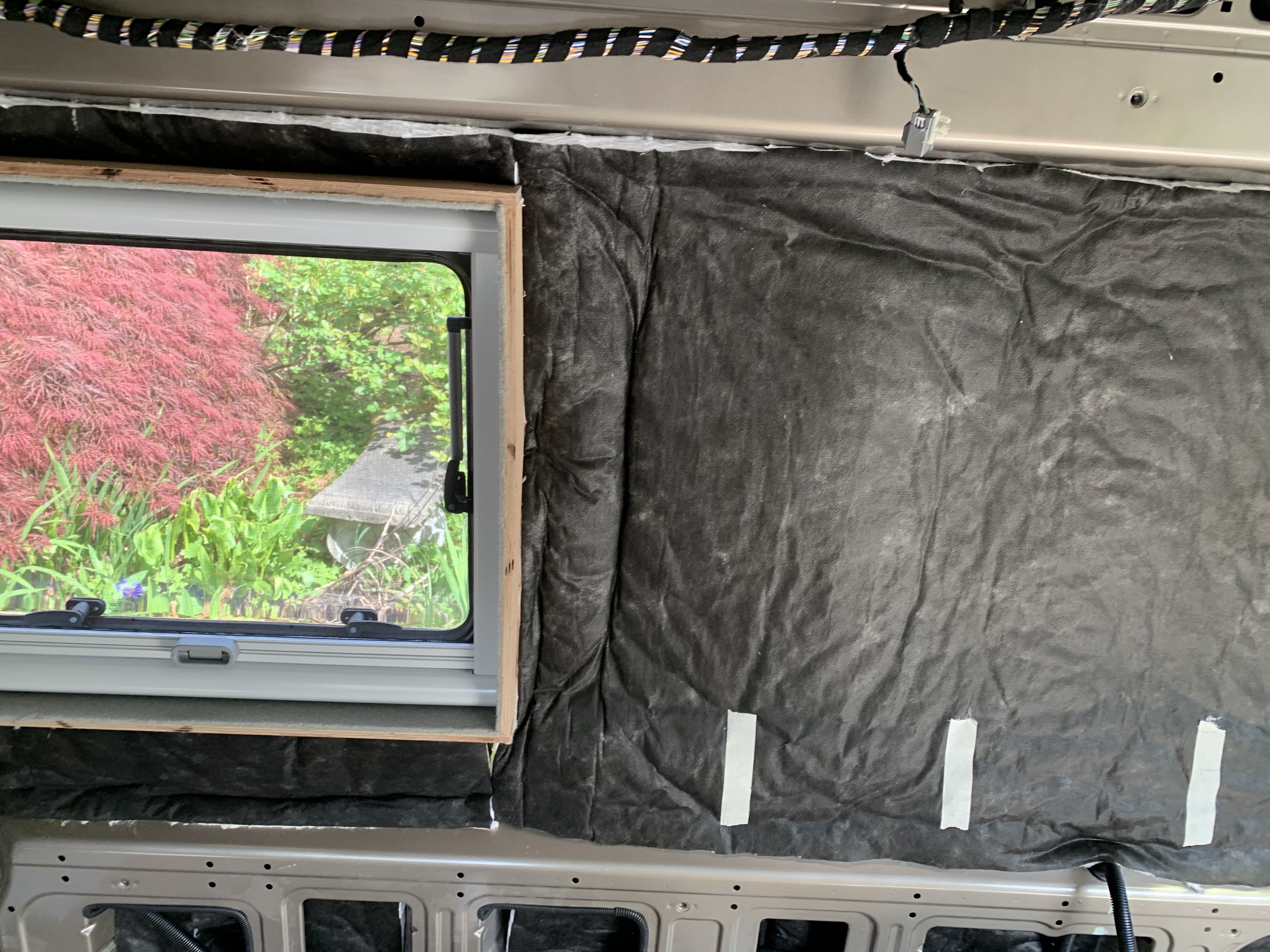
If you have seen many of my post it is obvious that I like to make diagrams, so of course I made diagrams how what I wanted my electrical system to look like. So, I will, throw up my diagram, that was the blueprint to building my electrical system.

While not 100% complete, the actual installation came out close.

The heart of the system is a
Lithionics LiFePO4 battery. Specifically model GTX12V555A-F25A-DIN40-MODULE.

It packs 555 Ahs or 7100 Whs of power, measuring 27 X 9 X 10.2 and weighing in at 119lbs. The battery has an external BMS, specifically the Advanced Plug a Play Never Die BMS. The BMS has the usual cell monitoring, balancing features, low & high voltage cut off. It has UL approved fully redundant protective safety circuit. It also comes with a built-in coulomb-based State of Charge meter. The connect and disconnect feature is done with uses a military grade latching contactor, supporting a maximum discharge of 400 amps. The BMS also supports can-bus, serial RS232, and an alternator field control circuit for communication with charging devices. Part of the reason, for such a large battery, was the to run an air-conditioner. Not specifically to run overnight, but when traveling with dogs, it is nice to be able to keep them cool during some lengthy stops.

The next part of the system is the
Xantrex Freedom XC Pro 3000 inverter/charger. It has a 5 second 2X surge rating and boast a 150-amp charger and a 50-amp transfer relay. The charger can be set in 5-amp increments, from 5-150 amps. It also sports load management features, that can dial back charger current, if other high current appliances are in use. The Pro model also supports Can-Bus and RV-C protocols, which should enable me to take advantage of the Can-Bus capabilities of the BMS. Part of the reason I chose this unit was the relationship between Xantrex and Lithionics. You can get a remote panel, that has blue-tooth for a phone app. I highly recommend this option just for the ease of set-up. It is still to early to decide if it was the correct decision on the unit, as I am a big fan of Magnum Energy.

I also installed a PWD30 -EPO -H, a hardwired 30 Amp Surge Protector with auto shutoff from
Hughes Autoformers. It has 2400 Joules of advanced surge protection, this is also replaceable module, so you do not have to purchase a whole new unit. A Smart circuit analyzer will shut down power if a dangerous event occurs. The power is delivered via a 30-amp
SmartPlug® shore power receptacle.

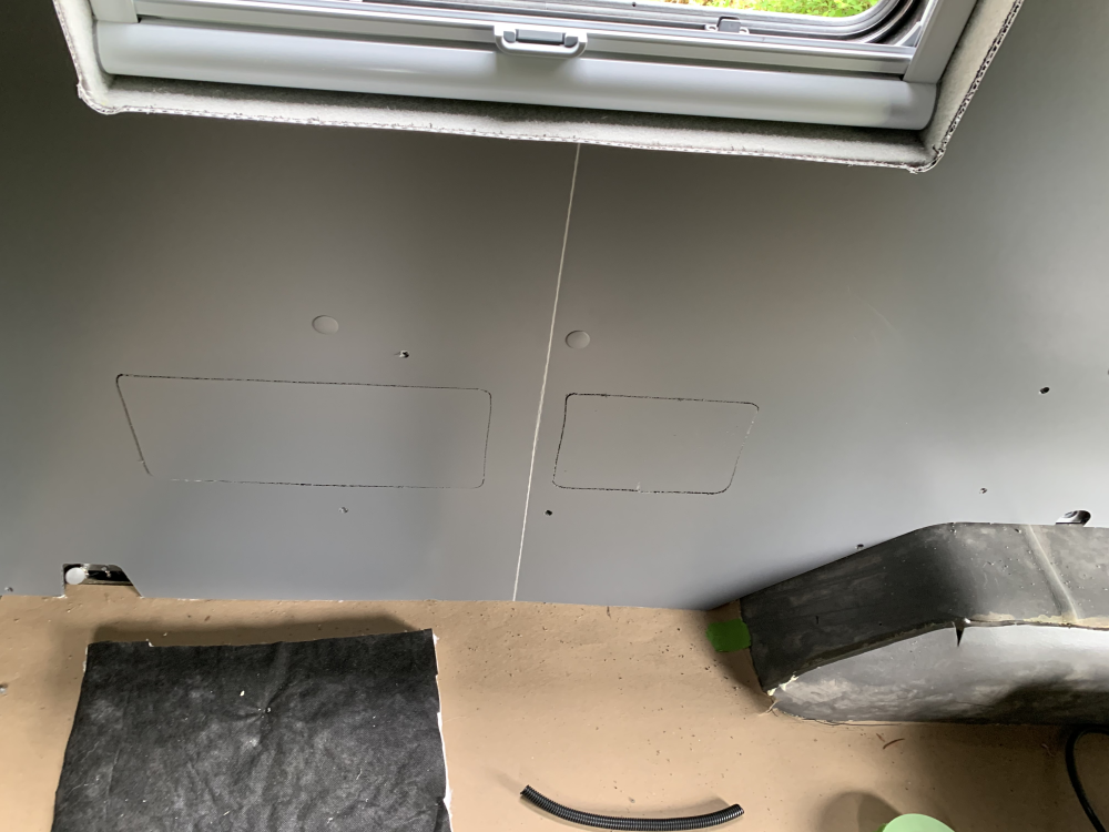
For distribution I built a quick cabinet that house that and some of the equipment controls. This cabinet has AC breakers on the top right side, DC breakers on the top left side, bottom left is the Bluetooth remote panel for the Xantrex inverter, the bottom right holds switches for BMS disconnect/connect and switches for solar panel control. The bottom middle is the Lithionics SOC meter. The middle middle is the Simarine Pico Battery Monitor System. The top middle is Remote panel for the Solar controller

For AC distribution I chose a
120 Volt AC Main + 2 Positions #1214 and
120 Volt AC 4 Position # 1210. This will give me a 30-amp main breaker, with six branch circuits. The branch circuits all come standard with 15-amp breakers; I need to change one of these to a 20-amp breaker for the air-conditioner. The remaining circuits will be fine with the standard 15-amp breaker. Those will be for the Truma Combi eco plus (heater/water heater), Passenger side outlets, Microwave, Driver side outlets, and finally a dedicated circuit for a small charger for the starting battery. Maybe I am getting old, but I did not want to have them at floor level. I built a quick cabinet to hold some of the equipment for testing. The only real problem in this location is access, I must make it so I can remove the panel for access, which can be challenging for wiring. The 1214 and 1210 breakers control the hot side, and give you a separate bus bar connection for the neutral and safety ground, I replaced those two smaller bus bars with a
Blue Sea DualBus Plus 150A BusBar - 1/4"-20 Stud 5 Gang #2722. It is larger so I can handle both units and has a cover.


Moving to the DC side of things, the first thing off the positive terminal of the battery, or in this case the BMS is a Class T Fuse. I used a
Blue Sea Fuse 5502 Fuse Block, with a 400-amp Class T fuse. While the Fuse block has its own cover, I went with a
Blue Sea MaxiBus Cover #2718. This gives nice coverage with an easily removable cover. A class T is a high-speed fuse, that boast a 20,000 Ampere Interrupt Capacity (AIC), which is a measure to interrupt currents without catastrophic failure. Remember My battery has a 1 second pulse current of 5500-Amps. Class T fuses are UL-248-15L listed and commonly recommended by inverter manufacturers.
From there I go to a busbar, in this case a
Blue Sea Powerbar 600A #2104, with a MaxiBus 2718 cover. You may have wondered why no disconnect switch for the battery, I have a switch to control the disconnect in the BMS, which kind of made the need redundant. From the busbar to we go to the XC Pro 3000 inverter/charger. The wire size remains 4/0 from battery to inverter, so everything is still covered by the Class T Fuse. The second branch off the busbar is to the
Blue Sea MRBF Surface Mount Fuse Block # 5196 for distribution. The 5196 is takes up a small are and can be useful in tight places. Again, I continue to run 4/0 wire to its input. From there I run an 80-amp fused circuit up to my main DC distribution.
For DC distribution I went away from normal tendencies (I am usually a Fuse guy) and installed two
Blue Sea 12 Volt DC 4 Position # 1216 , this enabled me to put some symmetry into my panel. At this point I should have probably designed a custom 360 panel, but I had already purchased the individual units. The number one position covers any thing in the front that is running off 12 volts. I have two circuits, an always on, and one that is hot only when the engine is in run, The number two is for night lights, or any thing that I generally only power at nighttime. The third position is for computer or entertainment. The forth is for auxiliary power or USB chargers. We finish out the rest of the panel with Lights, Fridge, Fans and Housekeeping.
The second attachment for the 5196 is for a Driver side fuse panel. At this moment slated to run a water pump, toilet flush, and more auxiliary power or chargers. I have run a 4 awg circuit over to that side of the van. I like to run a hefty wire to the opposing side of the van, for electrical distribution. It generally ends up being better for future upgrades and managing voltage drop.
The third attachment for the 5196 is being used more for an input, or specifically the solar controller. While I am running a 4 awg wire from the solar controller to and am fuse protecting at the controller, the fact that it is a tight run, I decide to fuse both ends. Coming out of the controller I use a
Blue Sea AMI / MIDI Safety Fuse Block # 7720. This block has its own cover, that can hold a spare fuse, and is ignition protected. I generally consider this my go to single fuse block.
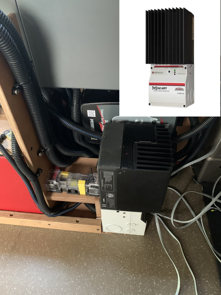
The controller is a Morningstar Tristar MPPT 60-amp controller. This is a solid performer that I use to have in my old rig. It has a high degree of programmability and voltage sense lines for accuracy. While it is possible to program with just the remote panel, I used a USB to serial RS232 converter using Morningstar MSview software.

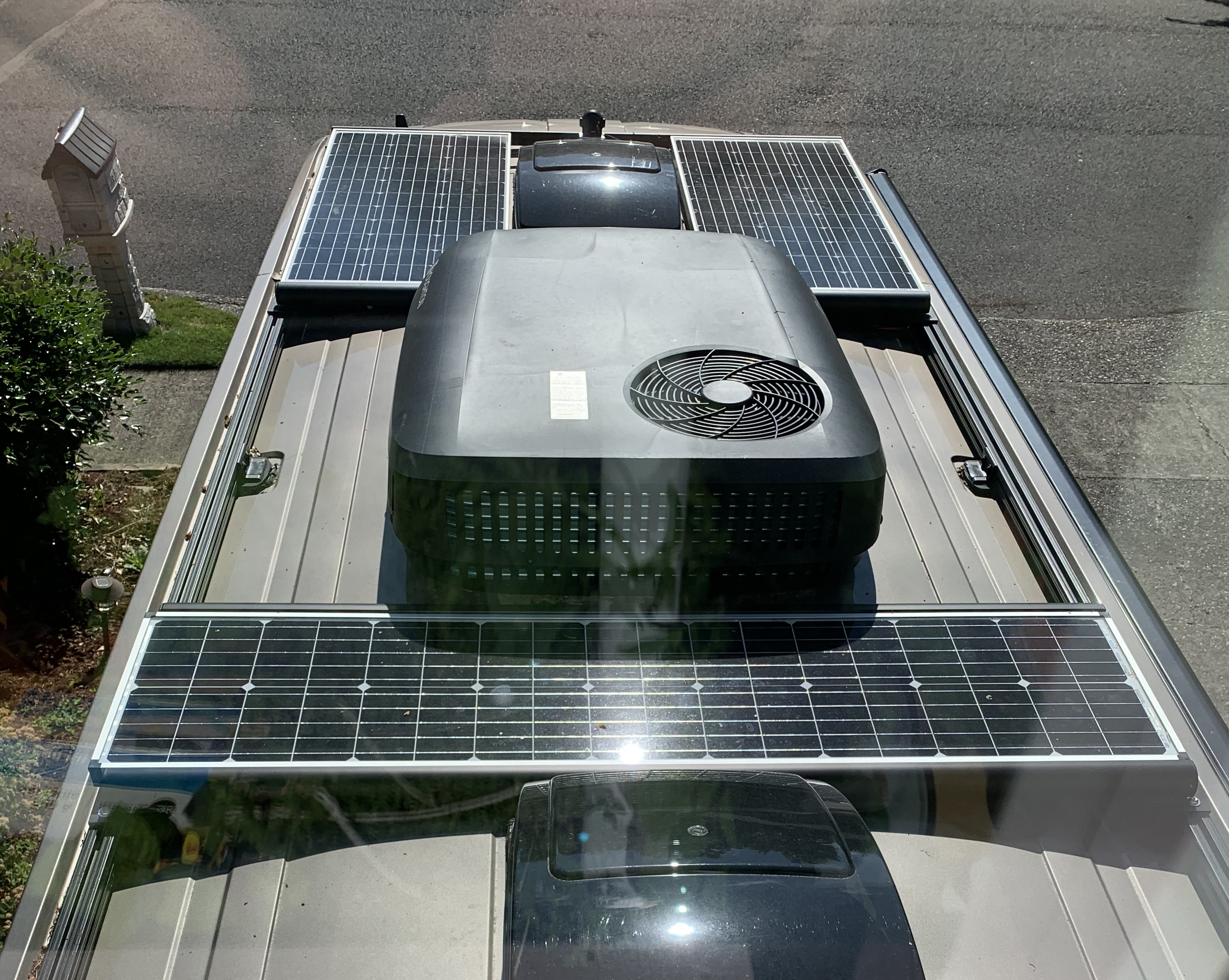
That moves us to the input of the solar controller. The solar input comes from my own combiner box. The box has five solar inputs, but the fourth and fifth are controlled together. I run each panel through the roof separately. I have a driver side panel, passenger side panel, a rear panel, and I have two auxiliary solar inputs on each side of the van. I decide to make the solar panels attach to my box with standard MC4 connectors, to do this I needed panel mount MC4 connectors. I found these Staubli PV-ADBD4-S2/6 Female MC4 Connector and Staubli PV-ADSP4-S2/6 Male MC4 Connector at
Solaris. I was also able to use it to downsize from the 8 awg wire from the panels to 10 awg inside the combiner box. The use or 8 awg was for voltage loss, not current capabilities. I ran all the positive inputs into a latching relay. This is in the form of a mini relay and works well in this application because once the state has changed, they do not use power. The downside is that I must use a second relay to control the indicator circuit for the switch, this will enable me to control each panel, the two aux solar circuits go through one relay. I use two inline MC4 fuse holders on the input of the two aux controllers. While any aux panels will have their own fuse, the input connections are accessible and are hot when the relay is on. I have another relay on the output of the driver side panel relay, this relay will divert the solar power from the main Tristar controller to a much smaller Victron controller that I am using to manage the two AGM Starting batteries. We go from the combiner box to the controller with 6 awg wire. The two sense wires will go from the controller to the connectors on the BMS.
The ground wires from the panels are diverted through a
Simarine SCQ25T quadra shunt. This is part of Pico Battery monitor system that I will get into a little later. This will enable me to monitor the power output of each panel, I will also be able to monitor the voltage of each panel and am monitoring the temperature of one of the panels on the roof. The ground wire from the solar controller diverts through its own
Simarine SCQ50 quadra shunt, in this case I am monitoring the output of the controller, not just the individual panels.
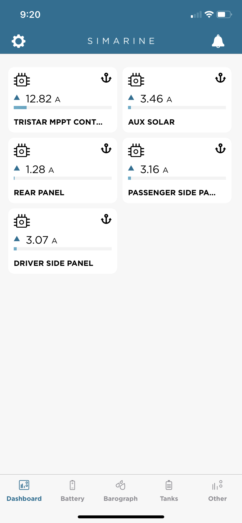
The Simarine screen above shows the total output of the controller and the individual panels. All the panels are close in size, but the rear panel seems to be a low performer. A quick glance and you can see the effects of shading from the angle of early morning sun.
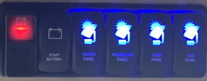
The four switches on the right control the individual relays in the control box. I found these switches at
OTR Switch Guys. I use four V - series V8D2U88B (on)/off/(on) SPDT switches to control the relays. These are momentary on switches; one position is wired to set the relay while the other position resets the relay. The switches have two independently wired blue LEDs. To the left of that is a V-series V1D1JBBB, the lower LED is independent, while the upper one is controlled via switch. This switch controls the relay to divert the positive output of the driver side panel to the Victron Solar controller dedicated to the start batteries. The final switch on the left is a Blue Sea #2145, I replaced the external switch to control the BMS disconnect. The old switch is a SPST (on)/off switch while the new one is a SPDT (on)/Off/(on). In this usage model the second momentary (on) position is redundant and tied together. The only remaining 12-volt power connection will come from the 2nd alternator from
Nations Alternator via a
Wakespeed controller. I expect it will be 3/0 or 4/0 awg wire. I will have more details on it when we finish the installation.
This leads me to the ground connections, normally I use a ST blade fuse block with grounds, so all the ground wires come back to the fuse block. The use of the Simarine system and the DC breakers made a common ground location sound like a better ideal. I chose a
Blue Sea Power Bar 1000 with 8 5/16th Terminal studs #1992. This gives me the capability of large bus bar with the 8 terminal studs, but it also provides both #8-32 and #10-32 connections. This provides the backbone of my ground circuits.
The battery or BMS attaches to the Power Bar 1000 via
Simarine SC501 Active shunt. This a 500-amp shunt that also monitor voltage at the Class T fuse. I attach to shunt to BMS with 4/0 awg cable, from the shunt to Power Bar I use
Link Bars that support op 650 amps. The link bars come in multiple lengths, and make short connections easily accomplished. The SC501 from the BMS is to monitor the battery, I also have another SC501 going to the Inverter. Although in most cases these to shunts will be measuring the same value, there will be differences that will now be easy to corelate.
I am currently using a Simarine SCQ50 and SCQ25 to monitor the current on the individual circuits. You can place these shunts on either the positive side or negative side of the circuit. I have chosen the negative side, the direction of the charge or discharge is configurable, so it can be switched easily. I will also use a SCQ25T on the driver side to measure water pump, etc. This unit will also measure the tank levels in the van. And the last SC501 shunt will be for the starting batteries.
The Transit can be ordered with a well thought out CCP or customer connection point. Previous year Transit had 3 x 60 amp fused connection point. The new CCP has 1x60-amp CCP1 circuit that is always on. The CCP2 circuit is a 1x175-amp connection that is controlled power. This is the primary location to connect electrical to the Transit charging system. Being that I am using an aftermarket second alternator, I will not be using the CCP for except to make a connection to the CCP1. The primary reason for this is to connect the two auxiliary chargers for the start battery system. I am using a
Victron Energy BPC121531104 Blue Smart Waterproof Battery Charger 12/15 with Bluetooth for a plug-in charger, this can be used when plugged in via the inverter. The second path for charging the start batteries is a
Victron Energy SCC075015060 Smart Solar MPPT 75/15 Charge Controller. This is a small solar controller to handle the incoming 100-watt panel, that can be switched over from the main house solar system. Both outputs connect with a
Blue Sea Dual Post connector #2016. We use a Blue Sea AMI / MIDI Safety Fuse Block # 7720 with a 30-amp fuse to run up to the CCP connection with a 6 awg wire. The ground connection goes to the ground bus bar witch is also tied into the transit frame.
-greg


 AWOL
AWOL


 Linear Mode