Journey with Confidence RV GPS App RV Trip Planner RV LIFE Campground Reviews RV Maintenance Take a Speed Test Free 7 Day Trial ×


Reply
 
Thread Tools Display Modes
 
Old 05-04-2023, 03:49 PM   #11
Senior Member
 
Join Date: May 2018
Location: Arizona
Posts: 670
I was really anxious to do a quick trial for cutting the fenders. I put together a set of pictures with annotations in a pdf file printed Powerpoint presentation. The highlights are in the figures below.

I got 1 1/4" out of it without trying too hard. I could probably squeak out an extra 1/4"-1/2" but that is probably it without major hackery.

I did not cut into the box that is below the pinch weld. That is where the extra 1/2" would have to come from with taking a pie cut out of the box and butt-welding it back together. Really not much additional work but it may make it harder to modify a Bushwacker if the bottom of the fender gets any narrower than what I show in this initial trial.

I will probably wait for any more aggressive cutting than that shown till I have a Bushwacker in hand.

Dropbox file here.

https://www.dropbox.com/s/5fhkbgmgep...ldMod.pdf?dl=0


Vehicle sustained frame damage from a hit to the passenger-side front fender.
• This series of photos is from a test fit trial to estimate how many wheels well space
can be gained with relatively easy cut and welding of the Fender and Pinch Weld
area.
• Poor fit of the entire fended is due to the prior wreck that totaled the vehicle.
• The main goal is to measure the reduction in the lower fended width.
• The lower fender was reduced by 1 ¼” in width
• This is just a trial before modifying the target vehicle which is a 2000 E-350-XLT EB
Attached Thumbnails
SummaryPage1.jpg   SummaryPage6.jpg  

posplayr is online now   Reply With Quote
Old 05-05-2023, 01:37 PM   #12
Senior Member
 
Join Date: May 2018
Location: Arizona
Posts: 670
I previously stated I thought I could get another 1/2" out of this mod, so I set about to see what was involved with cutting back the sheet metal box behind the pinch weld.

The bottom of this area is actually the furthest point forward at the back of the wheel well. So pushing it back (within reason) is the practical limiting factor for the maximum allowable Fender modification.

In summary, I was able to remove about 1 1/4" from this projecting box area. In order to realize this full amount of trimming you would have to remove an additional amount from the prior fender trim (1 1/4" by trimming the pinch weld and fender pie cut) which would be a total of 2 1/2".

The details are in a revised PowerPoint presentations.

https://www.dropbox.com/s/5fhkbgmgep...ldMod.pdf?dl=0
Attached Thumbnails
SummaryPinchWeldModPage9.jpg  
posplayr is online now   Reply With Quote
Old 05-06-2023, 06:19 AM   #13
Senior Member
 
Join Date: Nov 2019
Location: Denver Colorado
Posts: 820
posplayr. Thank you for such a great presentation!
__________________
2002 e350 window eb,
7.3
CCV high top
Conversion in process. Lol
Denver, CO
Lilnuts2 is offline   Reply With Quote
Old 05-06-2023, 10:30 AM   #14
Senior Member
 
Join Date: May 2018
Location: Arizona
Posts: 670
Quote:
Originally Posted by Lilnuts2 View Post
posplayr. Thank you for such a great presentation!
A little more PCAD (Powerpoint CAD) .

The main goal for me is to see if a 285/70-17 is feasible with just 2" of lift and by guestimating where and how much trimming is going to be required.

I used a post from TheLeterJ which showed a 5.5" lift and 285/75-17 tires on 17"x9" wheels. He trimmed 1" from the back of the fender and spaced the bumper out 1/2" and has no rubbing issues.

I called the size of the image so that the red circle is 3.4" in Powerpoint and then I can just shift the other circles representing different ride heights.

So I just estimated what would happen with variations in his lift as it goes back to stock. I rounded is 5.5" lift to 5" and then the steps are 2.5" each. The first yellow circle is labeled 2.5" (or actually 3.0") of lift. The next would be the stock label at 0.0" and then -2.5".

From this, we can see there is probably a diminishing return in trimming the back side beyond 2" . At a 2.5" ride height I would do some trimming of the bumper and possibly spacing as theLetterJ did.

Just to note, the picture is of a 285/75-17 which is nominally 34" whereas my 285-70-17 is just under 33" so I'm gaining another 0.5" in comparison.

In looking at what TheLetterJ did and the fact that he doesn't have a Bushwacker installed, I'm just going to go for a deep 2" fender cutback and foregone the Bushwacker option. I'm never going to go 4WD as I'm only looking for being able to extricate myself from accidental sand stuckage. I can air down my tires and refill with onboard air and in the future possibly add a rear air locker from ARB.


My next step is to increase the 1 1/4" fender cut (on the passenger side) to a 2" cut on the driver's side. This will come close to the cutback of the pinch weld and box just completed. Then I will mount a 285/70-17 on my 17x8" (-12mm offset) wheels and see what clearance I have. I can use a floor jack to increase the apparent ride height.
Attached Thumbnails
TheLetterJ_Lift.jpg   TheLetterJ_LiftVariation.jpg  
posplayr is online now   Reply With Quote
Old 05-06-2023, 05:01 PM   #15
Senior Member
 
Join Date: Feb 2014
Location: Santa Maria, CA
Posts: 586
Something to keep in mind is your scrub radius. As you turn, your tires will swing in an arc front to back (pivoting around the balljoint.) Even if it clears the fender opening while pointed dead ahead, it will still require a larger opening front to back to allow for the swing of the steering.

After those 285/75/17's wore out, I replaced them with 315/70/17's and had to trim more. I trimmed the front bumper similar to what you posted, and all was well for awhile. My next (current) set of 315/70/17's ended up being slightly taller, and a fair amount wider than my last set of 315's and I had to trim even more. I ended up with a Weldtec bumper so there aren't any clearance issues there, but I had to go for broke at the back of the fenders. I drilled a new hole behind the OEM lower mounting bolt, installed a bolt in the new hole, and cut the fenders to about the backside of where the old hole was. The narrowest part of the lower/backside of my front fenders is now no more than 1" and the cut extends roughly 10.5-11" upwards from there. I also had to bend the outer corners of the lower seam of the core support/inner fender forward as my tires had left a polished spot right there. So far, so good, but I haven't driven my van in anger offroad since those changes.
TheLetterJ is offline   Reply With Quote
Old 05-07-2023, 04:11 PM   #16
Senior Member
 
Join Date: May 2018
Location: Arizona
Posts: 670
Quote:
Originally Posted by TheLetterJ View Post
Something to keep in mind is your scrub radius. As you turn, your tires will swing in an arc front to back (pivoting around the balljoint.) Even if it clears the fender opening while pointed dead ahead, it will still require a larger opening front to back to allow for the swing of the steering.
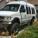
I did some more PCAD to visualize what starts to hit when turning the wheels. I labeled this as Tire sweep rather than scrub radius.

I measured the distance from the balljoint's center to the rim's inside edge for my 17"x8" -12mm wheels; it was about 1" even though the side wall bulges out closer to the balljoint turn center.

I show three tire profiles for -25,0,+25 degrees from the top down. The rectangle is the tire height x tread width ignoring bulging side walls. I just picked 25 degrees; I did not actually measure it.

To keep everything straight I showed a nominal required wheel well as well as some dimension of required internal space.

Trying to deal with the variations in wheel size and offset was a little beyond the accuracy of this simple analysis so I just kept the inside wall of the tire at the same spot for all the variations.

The little ball in the center represents a turning radius of the inner rim with the previously mentioned 1 " offset from the ball joint center.

So it is clear that the main issue with tire clearance is going to be on the inside rear of the wheel well when turning the fount of the tire out.

The first thing to cut back is the outside portion of the wheel well (requires corresponding pie cuts from the fender as well) as I show in the pictures and then make sure the suspension is lifted enough to keep the floor well above the tire with a compressed suspension. Otherwise, you will rub on where the floor meets the air vent humps.


Quote:
Originally Posted by TheLetterJ View Post

The narrowest part of the lower/backside of my front fenders is now no more than 1" and the cut extends roughly 10.5-11" upwards from there.
Did you have to go any further than the picture that I showed which cuts off the pinch weld and cuts out a pie section from the inner/outer side walls (shown as 1 1/4" in front of the door?

The next level is to actually cut a pie section out of the floor where the inner wheel well meets the floor in the front seat foot area. This requires pulling back the carpet and any wires running at the base of the wall.

This area is probably the driving limitation for putting lift into the front end. You need lift to get the floor above a significant portion of the tire and still allow for spring compression.

Quote:
Originally Posted by TheLetterJ View Post

I also had to bend the outer corners of the lower seam of the core support/inner fender forward as my tires had left a polished spot right there.
Is this in the front or the rear?
Attached Thumbnails
Composite_TireSweep.jpg   FloorPieCut.jpg  
posplayr is online now   Reply With Quote
Reply


Posting Rules
You may not post new threads
You may not post replies
You may not post attachments
You may not edit your posts

BB code is On
Smilies are On
[IMG] code is On
HTML code is Off
Trackbacks are Off
Pingbacks are Off
Refbacks are Off

» Sportsmobile Registry

At-At

Dirk/co

Esme

Amy V
Add your Sportsmobile
» Featured Campgrounds

Reviews provided by

Powered by vBadvanced CMPS v3.2.3
Disclaimer:

This website is not affiliated with or endorsed by Sportsmobile SIP or any of its affiliates. This is an independent, unofficial site.


All times are GMT -6. The time now is 08:10 PM.


Powered by vBulletin® Version 3.8.8 Beta 4
Copyright ©2000 - 2024, vBulletin Solutions, Inc.