Journey with Confidence RV GPS App RV Trip Planner RV LIFE Campground Reviews RV Maintenance Take a Speed Test Free 7 Day Trial ×


Reply
 
Thread Tools Display Modes
 
Old 08-24-2012, 06:39 PM   #561
Site Team
 
WVvan's Avatar
 
Join Date: Jul 2009
Posts: 1,293
Re: Hal The Van

Upgrading the Blower Motor Controls - Post #4

Now that I've installed the new blower motor PWM control module inside the dash I have to decide how to wire this up to the blower motor. Could always run new wires but since there is already wires in place I'll use them instead. The old wiring will need a little reconfiguring.

Start with a look at the original blower motor wiring. This diagram shows how the "Function Selector Switch" is wired. The "Function Selector Switch" is the one on the CCC marked "MAX A/C, NORM A/C, VENT, OFF, FLR, MIX, defrost symbol"


Note how when the switch is in any position except "OFF" power flows through the switch to the "Blower Motor Relay".


The letter "A" in the triangle means this circuit is continued onto another page


This page shows the continuation of the blower motor circuit.


The "A" in the triangle shows the power coming from the "Function Selector Switch" and energizing the coil on the "Blower Motor Relay". The relay makes the connection between the blower motor and van battery through the 50 amp fuse at position number 13 in the "Engine Compartment Fuse Box".


I no longer want the power to go directly to the blower motor but instead want it to go to the PWM control module installed in the dash. The power for the motor will then come from the PWM control module. So I need to bypass the motor. In the above diagram the connector for the motor is labeled as "C160". The wires for C160 are labels as "O/R" and "O/BK". So one wire will be orange with a red strip and the other will be orange with a black strip.

Here is connector C160.


Normally this connector would be plugged directly into a socket in the side of the blower motor but I previously installed a replacement blower motor. The replacement motor came with this externally wired socket that connector C160 plugs into instead.


On the replacement motor's external socket cut both the wires. Then strip and crimp the two wires together at the socket. I'll come back to the wires that lead to the motor.


Double shrink tube the connection to try and make it weather proof.


With the blower motor bypassed the power goes from circuit #515 into circuit #261. There is a splice at S144 where the circuit branches to both the left and the right. Ignore the right branch to the "Blower Motor Resistor" for the moment and follow the circuit to the left. The circuit terminates at the "Front Blower Switch" through connector C207.


Here are details of the blower switch and connector C207.


Connector C207. It plugged into the back of the CCC.


By crimping spade connectors to the ends of wires I can plug directly into the connector. This way I didn't have to cut the wires from the back of the connector.


The spade connectors are on wires that led to the PWM control module. That's how I'll get power to the module and also using it to send the modulated power back to the blower motor.


Same diagram as before. Notice circuit #269 (LB/O) and #260 (R/O). They run from the connector C207 to connector C158.


Here is connector C158. It's plugged into the "Blower Motor Resistor".


In the new wiring scheme the "Blower Motor Resistor" is no longer used so I'm going to take circuits #260 and #269 and use them to deliver the Pulse Width Modulated power to the blower motor. I've already wired it up at the connector C207 end. Crimp spade terminals to each of the two motor wires I cut earlier. Plug them into connector C158 in the appropriate slots. This is a DC motor so polarity does matter.


I'm only going to use two of the four slots in the connector. To make the connection weatherproof I painted on several coats of the Liquid Electrical Tape.


Plug in the bypass to connector C160.


Cable tie wires in place.


In this new arrangement the "Blower Motor Resistor" is no longer used. Will leave it in place because to remove it would leave a hole in the ductwork.


Put the two halves of the CCC back together now with the power LED and pot speed controller installed.


Found one problem when I first tried to use the new blower speed control. It will only turn 90 degrees. I had assumed that the original fan speed selector switch is what restricted the turning arc and once the switch was removed it would turn freely. Not so. You can see this plastic ridge that limits the knobs turning to 90 degrees.


It engages this small clear plastic block on the knob.


A little surgery with a Dremel and no longer a problem.


The knob will now turn through the pot's full turning arc of around 300 degrees.


Put it all back together.


I wired up one of toggle switches below the radio so I can run the fan from the house batteries. It's wired up similar to how I have the radio so the fan power automatically switches over to the van battery whenever I start the engine.

I've put a thousand + miles on the van since doing the fan upgrade and I really like it. Having more than four speed settings is nice when driving and being able to power vent the van when camping comes in handy. I wouldn't run the fan at high speed for too long when on house batteries alone but you can still get a nice air flow at low speed which isn't too hard on the batteries.

At night the blue LED is a brighter than expected but since it's pointed at the center of the van it's not a distraction to me when driving. In case you forget to set the vent control before stopping the engine it's no problem since there is still enough vacuum left in the system to change vent settings.

OK. That's the end of this project.

__________________
Open the pod bay doors Hal.

Once I exit Hal, this is what I do.
https://larry.wvnet.edu/~van/pics/lic...late-small.jpg
WWW.WVBIKE.ORG
WVvan is offline   Reply With Quote
Old 08-24-2012, 08:58 PM   #562
Senior Member
 
BIGVANS's Avatar
 
Join Date: Feb 2012
Location: Up In The Mountains
Posts: 427
Re: Hal The Van

Quote:
Originally Posted by WVvan
OK. That's the end of this project.
You know that's not true!!!


By the way, looks great!
__________________
2003 Ford E-350SD 4x4
V10 / 4R100 / NV271
Front Axle - 1 Ton Spec Dana 60/King Pin/Open Knuckle/High Steer
Rear Axle - 1 Ton Spec Dana 60/Full Floating
Eaton E-Lockers Front And Rear/4:10 Gears
ARB Differential Covers - Nodular Iron With Dipstick And Drain Plug
Leaf Spring Suspension Front And Rear
46 Gal Transfer-Flow Fuel Tank
ExtremeAire Magnum Air Compressor
Reunel Rear Bumper
On And On ...
BIGVANS is offline   Reply With Quote
Old 08-24-2012, 09:41 PM   #563
Senior Member
 
twogone's Avatar
 
Join Date: Aug 2010
Location: Taylor, Mississippi
Posts: 1,648
Re: Hal The Van

Once again...

You might jus be a daynjusmain
__________________
'95 SMB E350 Quigley 7.3
https://www.taylorarts.com
... If you have to ask, you'll never understand...
"... torpedo'd, because we don't generally cotton to bullshit around here." -jage
"... do they ooch apart in the night?" -Dia
twogone is offline   Reply With Quote
Old 08-25-2012, 06:44 AM   #564
Senior Member
 
Gnarvan's Avatar
 
Join Date: Dec 2011
Location: Washougal, Wa
Posts: 1,047
Re: Hal The Van

I'm going to have to pick up some of that liquid electrical tape. I can see a lot of applications for that stuff. Thanks for giving me more ideas that will make my wallet a little skinnier.
__________________
John

Gnarvan 1992 E350 Clubwagon
Advanced 4WD Systems Conversion

Sotar Legend 12.5' X 22" Cataraft
2003 BMW R1150GS-Adventure
2013 BMW R1200GS-Adventure
Gnarvan is offline   Reply With Quote
Old 08-31-2012, 08:11 PM   #565
Site Team
 
WVvan's Avatar
 
Join Date: Jul 2009
Posts: 1,293
Re: Hal The Van

Quote:
Thanks for giving me more ideas that will make my wallet a little skinnier.
You've discovered the secret of the Sportsmobile Forum. The more time you spend here, the less money you own.

So about a half hour ago I hop into the van to run a couple errands and start pulling away from the house. When I first use the brakes they feel a little soft. When I use them a second time they go to the floor. If you've noticed from my photos I live on a bit of a hill. Luckily when this happened the van was pulled around so it was perpendicular to the slope. Carefully moved it back to in front of the house and saw this when I got out:


Some people might be distressed to have this happen to them but not me. Why? Because I spent last weekend camping at the Monongahela National Forest in the van. So that means it is was a weekend of up the mountain, down the mountain, up the mountain, down the mountain, up the mountain.... You get the idea.
The fact that this might easily have happened while barreling down a steeply graded, no guard railed forest road miles from help but instead happened while I was moving along slowly a few feet from my house means I'm happy as can be.

Seeing how it's a three day weekend and I wasn't planning to go anywhere I'll have plenty of time to work on the problem.
__________________
Open the pod bay doors Hal.

Once I exit Hal, this is what I do.
https://larry.wvnet.edu/~van/pics/lic...late-small.jpg
WWW.WVBIKE.ORG
WVvan is offline   Reply With Quote
Old 10-01-2012, 09:01 PM   #566
Site Team
 
WVvan's Avatar
 
Join Date: Jul 2009
Posts: 1,293
Re: Hal The Van

Got the brake system replacement done today.


Didn't document it like usual since it's a really dirty and greasy job and didn't want to mess up my camera.

cost:
Rock Auto
rear brake hose: $14.96
left front brake hose: $13.09
right front brake hose: $14.23

Advance Auto
brake caliper - $44.99 excluding core charge (needed two)
brake pads (Wearever Gold) - $37.89
nickle-copper brake line - 3/16" x 25' - $49.99 (needed two)
brake fittings - 3/16" x 3/8" (5 fittings per package) - $1.99 (needed two)
brake fittings - 3/16" x 7/16" (5 fittings per package) - $2.49 (needed two)
brake fittings - 3/16" x 9/16" (5 fittings per package) - $2.49
brass union - 3/16" x 3/8" - $2.49
brake hose retaining clip - 4 clips per package - $5.49
wheel cylinder - $15.19 (needed two)
brake drum hardware kit - $8.49 (one kit covers both rear wheels)
brake fluid - 32 oz - $5.99 (needed three)
bolts - M8-1.25 x 12mm (needed for one wheel cylinder) - $2.49

Harbor Freight
Double flaring tool - $19.99 - (See more about this farther down)

One blood blister - no charge

Following is some information that would have made the job easier if I'd known it all ahead of time:
Brake fittings and brake line runs. All brake lines are 3/16".

Rear most fitting on the master cylinder. 7/16".
This line runs to the right (drivers) side of the ABS unit directly below the master cylinder.


Front most fitting on master cylinder. 9/16".
This line runs to the top of the brake hose that goes to the drivers side caliper.


Both the fittings on the ABS unit are 7/16".
This line runs down to then along the top of the drivers side frame rail. Aft of the front wheel it runs to the outside of the frame until opposite the fuel filter then curls over the top of the rail to a union.


Top of the brake hose for the driver's side caliper. There are two 3/8" fittings here. One you can see entering at the top and another on the back. One fitting is from the master cylinder. The other goes to a brake line that runs to the passenger side brake hose. The brake line that runs to the rear wheels is visible in the ceter right of the photo.


Brake hose for the passenger side caliper. The 3/8" fitting enters in the rear.


Rear brake hose. This also a 3/8" fitting. This length of brake line runs from the union near the fuel filter along the inside of the frame rail parallel to the fuel tank to this point. One note about the rear brake hose. The old hose was so rusted to this metal support I had to first use a sawzall to cut away one side of the fitting then use a hammer, punch and some violence to get it free.


Bottom of the rear brake hose. Left fitting is 7/16". It runs to the drivers side wheel cylinder. Right side is 3/8" and runs to the passenger side wheel cylinder.


Both left and right side wheel cylinders use 7/16" fittings.


The two bolts that hold each wheel cylinder take a 10mm socket to remove.


To remove the front calipers you'll need a 13/16" socket for the brackets and a 1/2" for the caliper bolts.


To get the caliper core charge back you'll need to include the bracket. Funny thing about the core charge at Advance Auto. The core charge was more expensive than the new calipers.


Bleed screws. For the wheel cylinders it's 3/8". For the passenger side caliper it's also 3/8" but for the drivers side caliper it's 10mm.


I decided to use nickle-copper brake line as a replacement to steel brake lines for three reasons. It doesn't rust. It's easy to bend and I'll be able to make the needed double flared ends using a cheap Harbor Freight tool.


The reviews for the Double Flare tool on the Harbor Freight site show that it's not tough enough for steel brake line but I hoped it would work well enough with nickle-copper. Almost. A lot of the reviews complained about the small post on the round die snapping off. I was careful with the tool as I made the flares but on, what I thought would be, my last flare the same thing happened with the post snapping off. So I took a larger sized die and used my metal lathe to reduce the diameter of the center post then shortened it.


Here is the broken die next to the newly machined one.


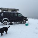
I'd like to say that everything was just right when I went to bleed the system but that would be a lie. Two of my flares leaked and needed redone. Here I am under the van doing the one that attaches to the rear brake hose.


I'm being closely watched to make sure I get it right this time.
__________________
Open the pod bay doors Hal.

Once I exit Hal, this is what I do.
https://larry.wvnet.edu/~van/pics/lic...late-small.jpg
WWW.WVBIKE.ORG
WVvan is offline   Reply With Quote
Old 10-02-2012, 07:46 AM   #567
Senior Member
 
86Scotty's Avatar
 
Join Date: Jul 2011
Location: TN
Posts: 10,242
Re: Hal The Van

Nice work. I envy your patience and attention to detail as always.

Sorry about the driveway, that may be the only permanent scar.

86Scotty is offline   Reply With Quote
Old 12-04-2012, 08:52 PM   #568
Site Team
 
WVvan's Avatar
 
Join Date: Jul 2009
Posts: 1,293
Re: Hal The Van

I've gotten a few private messages worried that something had happened since there hasn't been any new Hal postings in a while. Mainly I've been doing a lot of traveling. That and with the shorter days it's dark by the time I get home from work which always puts me into a bit of a funk this time of year. Well things are now looking brighter. According to the U.S. Naval Observatory tomorrow is the last day this year when the sun sets earlier than the day before. By 12/9 it will start setting later even thought the Winter Solstice isn't until 12/21. The days will continue to get shorter until then but that will be from later sunrises. Science!

Back to work. With all the interstate traveling I've been doing in Hal lately there is a steering problem that's really started to bug me. At speeds above 60 MPH the steering wheel has a slight back-and-forth shimmy that's tiring on a long haul. I've previously had the ball joints and alignment checked and tires rebalanced but it won't go away. I'd read about adding a steering stabilizer so decide to give it a go. I should have done this years ago.

I used this thread from http://www.ford-trucks.com as my guide for this project.

Here are the three main components needed for this project.


Same parts, different view.


The two brackets I ordered from www.silverstatefordparts.com

Part #s
F2UZ3E652A $38.10
F2UZ3E652B $56.70 (The "B" bracket is the one with the two U-bolts)

The Monroe Magnum Steering Damper came from my local Advance Auto.
Part # SC2955 $33.99

First off is to locate the "A" bracket. It goes on the the left hand (passenger side) chassis frame at the front. Here are the three mounting holes on my van.


There were rust issues with Hal when I bought it. I've covered the exposed metal with Rust Bullet to deal with the rust. Need to first knock off any surface rust before installing the bracket so do some chipping. Next take a 3/8" tap and clean up the mounting holes.


After checking the metal vs rust ratio in the tapped hole I had my doubts about the threads holding power.


So I threaded in a 3/8" bolt and tried to see if I could strip the hole.


Yep I could.


Went back to my tap set and found the next largest size which is 7/16" and used it next.


Can't tell from the pictures but I'm using cutting fluid with the tap.


This time the tapped holes looked a lot better. Tested them the same way as before but this time with a 7/16" bolt. The holes didn't strip.


Bolt the "A" bracket to the frame using three 7/16"-14 X 1" bolts with lock washers. All the hardware store had in that size was Grade 8. Bolts were $1.09 each and washers $0.22 each.


Do the "B" bracket next. First off I measured the max extension of the piston on the steering damper. It's around 8".


Before proceeding, turn the wheels all the way to the right. This is needed to align the "B" bracket.

Next is to attach the damper to the "A" bracket. I used a 1/2" bolt but it had to be pounded through the Monroe damper. A better fit would be with a M12-1.75 bolt but I didn't have any on hand.


Extend the piston about a 1/2".


Then use that to line up where the "B" bracket should be bolted to the drag link on the van.


Since the "B" bracket can be rotated on the drag link while still keeping the piston extension at 1/2" it's not obvious what the best position should be. I used the rubber heater hose as a guide so none of the steering damper parts would rub against it and possibly cause a hole.


The bolt that extends from the "B" bracket through the Monroe damper is a M12-1.75. I paid $1.04 for a pair of nylon locknuts for it. Snug up all the nuts on the "B" bracket but don't do a final tighten yet.

Turn the front wheels all the way to the left and check the fit.

Here's why I measured the max piston extension earlier. Can check if the damper is fully extended. There is still have another inch if needed.


It would probably be best to have someone observe the the steering damper as you turn the wheels back and forth. When you're sure everything looks good tighten it down.


Take it for a test drive. In my case the steering damper has made a major improvement in the steering wheel shimmy. It's not totally eliminated but much better. I've read of other benefits but haven't had a chance to really test it out yet.

That's it.
__________________
Open the pod bay doors Hal.

Once I exit Hal, this is what I do.
https://larry.wvnet.edu/~van/pics/lic...late-small.jpg
WWW.WVBIKE.ORG
WVvan is offline   Reply With Quote
Old 12-05-2012, 08:44 AM   #569
Senior Member
 
twogone's Avatar
 
Join Date: Aug 2010
Location: Taylor, Mississippi
Posts: 1,648
Re: Hal The Van

It's a shame that your damper doesn't have a big ol' gaudy red rubber boot on one end like mine
__________________
'95 SMB E350 Quigley 7.3
https://www.taylorarts.com
... If you have to ask, you'll never understand...
"... torpedo'd, because we don't generally cotton to bullshit around here." -jage
"... do they ooch apart in the night?" -Dia
twogone is offline   Reply With Quote
Old 12-05-2012, 08:52 AM   #570
Site Team
 
WVvan's Avatar
 
Join Date: Jul 2009
Posts: 1,293
Re: Hal The Van

Basic black is kind of boring. Guess I'll have to paint it silver so it better blends in.
__________________
Open the pod bay doors Hal.

Once I exit Hal, this is what I do.
https://larry.wvnet.edu/~van/pics/lic...late-small.jpg
WWW.WVBIKE.ORG
WVvan is offline   Reply With Quote
Reply


Posting Rules
You may not post new threads
You may not post replies
You may not post attachments
You may not edit your posts

BB code is On
Smilies are On
[IMG] code is On
HTML code is Off
Trackbacks are Off
Pingbacks are Off
Refbacks are Off

» Featured Campgrounds

Reviews provided by

Powered by vBadvanced CMPS v3.2.3
Disclaimer:

This website is not affiliated with or endorsed by Sportsmobile SIP or any of its affiliates. This is an independent, unofficial site.


All times are GMT -6. The time now is 01:45 PM.


Powered by vBulletin® Version 3.8.8 Beta 4
Copyright ©2000 - 2024, vBulletin Solutions, Inc.