Journey with Confidence RV GPS App RV Trip Planner RV LIFE Campground Reviews RV Maintenance Take a Speed Test Free 7 Day Trial ×


Reply
 
Thread Tools Display Modes
 
Old 07-05-2020, 05:57 AM   #1
Senior Member
 
Scalf77's Avatar
 
Join Date: May 2007
Location: Beaverton, OR
Posts: 2,478
Battery Isolators, Separators, Switches & More (updated 2020)

Battery Isolators, Separators, Switches & More (updated 2020)

It has been a while since I first posted this thread, so I thought it might be a good time to update. The primary reason is the technology itself; we tend to have more options out there today than there was before. Also, my own knowledge and usage model has progressed and changed over the years as have some of the pros and cons of possible solutions.

The first and most important thing to remember is that there really is no one perfect solution, depending on our electrical needs and/or vehicle one solution may be better than the other. What works for camper A may not be the best solution for camper B. The second thing is that these solutions are still dependent on the alternator for power.

Alternators are typically referred to by their max ratings, I have a 140-amp alternator, or I upgraded to a 250-amp alternator. What does that really mean? Luckily, there are standards for measurements. Both ISO 8854 and SAE J 56, alternator testing and labeling standards indicate that the “rated output” of an alternator is the amount of current that it can produce at 6,000 RPM. They also refer to idle speed, which really depends on the standard, but usually can be referenced to 1,500 RPM. This is referring alternator shaft rotation not engine RPM. Typical labeling of an alternator requires a format of “IL / IRA VTV,” where IL is the low, or idle, amperage output, IR is the rated amperage output, and VT is the test voltage.

A common example is 50/120A 13.5. Here 50 refers to the current provided at idle or the “low” test speed. The 120 refers to the “rated” test speed, this is generally the number used for the rated output, as in I have a 140-amp alternator. And then we have VT, which is the voltage that the alternator was held at during the test. The actual rating will go up or down based on the voltage output setting of the alternator in your vehicle.

The important thing to remember is that the output of your alternator is load dependent. Just because it has a rating of 140-amps does not mean that it is always putting out 140 amps (or 50 amps at idle). This is controlled by another important part of the charging system, the voltage regulator.

The regulator is usually internal to the alternator, but on some vehicles it is external. Even if the regulator is internal, the control of that regulator may be back at the PCM or ECU. As with anything controlling the output of the alternator with a computer can be both simpler and more complicated. Still the basic principle is more load on the alternator drops the voltage, the alternator must increase its output to keep it at the voltage setpoint. The inverse is true, with a reduced load the alternator reduces the current, so that the voltage does not go too high.

Then of course a lot will depend on your rig, we can take the E350 in a V10, and it is relatively tolerant to lower voltage. if you have the 6.0 diesel you have components like the FICM that is much less tolerant to lower voltages. We also have housekeeping load on the RV side. Some rigs may have a very low load for their housekeeping footprint, while others may have Starcool or run their inverter while driving. Typically, in my rig if I have the battery below 70%, Starcool (rear air conditioning) fan on high and running onboard entertainment systems the housekeeping load is too high for the alternator at idle. Turning the Starcool blower to low would alleviate the potential problem.


Switches

Let us go back to the simple battery switch. We have a hard switch that you can purchase for the possible current needs you have. All this switch does is put the starting battery in parallel with your house battery system. We simply close the switch when the van is running and allow our existing alternator system to charge the house battery and housekeeping loads.

Pico 5575pt Master Batt Isolator Switch

  • 2 Position On-Off with Removable Key
  • 3/8" x 3/4" Length Studs, 4 3/16" Mounting Holes in Base
  • 12 Volt 350 AMP DC Continual,
  • 12 Volt 500 AMP DC Momentary (10 Seconds)

Blue Sea m-Series Mini On-Off Battery Switch with Knob – Red #6006

  • Single Circuit On-Off
  • Maximum Voltage -------------- 48V DC
  • Continuous Rating -------------- 300A
  • Intermittent Rating -------------500A (5 min)
  • Cranking Rating 30 sec. --------900A
  • Cable Size to Meet Ratings --- --4/0 AWG (120mm²)

Blue Sea e-Series On-Off Battery Switch #9003e

  • Single Circuit ON-OFF
  • Maximum Voltage -------------- 48V DC
  • Continuous Rating -------------- 350A
  • Intermittent Rating -------------600A (5 min)
  • Cranking Rating 30 sec. --------1200A
  • Cable Size to Meet Ratings------4/0 AWG (120mm²)

Marinco Contour Battery Master Switch #701

  • Single Circuit On-Off
  • Maximum Voltage ------------- 48V DC
  • Continuous Rating ------------- 275A
  • Intermittent Rating ------------ 455A (5 min)
  • Cranking Rating 30 sec. ------- 1250A
  • Cable Size to Meet Ratings-----1/0 AWG (120mm²)


While all these switches can do the job, some might meet the needs of your rig better than others, notice the Blue Sea Systems® & Perko® switches have a Cranking Rating 30 sec, which could be important if you plan on using your house battery for emergency starting. You should also notice one other important part of their specification, Cable size to meet ratings 4/0 and the note * Reducing cable sizes will reduce current ratings. If you have question on the reduced ratings it would be best to contact Blue Sea Systems® directly for feedback.


Since the switch just puts the two electrical systems in parallel, one could use the same switch to charge both the house battery and van battery from either shore power charger or solar charger. But again, it is a manual switch.

While this is a simple solution it has some drawbacks, the primary is that you need to manually turn the switch. So, you need to remember the open or close the switch. It is also difficult to position the switch, as it must carry a fairly large size wire but still be accessible.

Scalf77 is offline   Reply With Quote
Old 07-05-2020, 05:58 AM   #2
Senior Member
 
Scalf77's Avatar
 
Join Date: May 2007
Location: Beaverton, OR
Posts: 2,478
Solenoids

Since an inline manual switch maybe hard to locate, we move to a high-power solenoid. The solenoid can be in line, but the actual 12-volt control switch can be positioned in a location that is convenient. While this generally helps, you still must remember to use the switch. It must be a continuous duty solenoid, and thus when closed it will draw some amount of power.

This is a Cole Hersee 12V, 200A Continuous Duty Solenoid, it is very standard solenoid. You may also find this with three terminals, as the grounded and the ground connection comes from it being attached to the grounded body.


  • Single Circuit ON-OFF (SPST)
  • Normally Open Contacts
  • Maximum Voltage--------------12V DC
  • Continuous Rating--------------200A
  • Intermittent Rating-------------NA
  • Cranking Rating 30 sec.--------NA
  • Cable Size to Meet Ratings-----NA


The Trombetta Bear DC Contactor part# 114-1211-010 or 114-1211-020. This is the solenoid that Surepower used for their separator. There is one very important thing to check for and that is cycle life. A lot of that is dependent on the material used for the contactor inside, we see that standard copper specs 25K, but silver will give us 50K. If going this route, the -020 would be the better choice. A couple of other important specifications that gave us was pull in voltage, hold voltage, and coil resistance. These will become more important later in the document

  • Single Circuit ON-OFF (SPST)
  • Normally Open Contacts
  • Maximum Voltage----------------------- 12V DC
  • Continuous Rating-----------------------225A
  • Intermittent Rating----------------------600A
  • Cranking Rating 30 sec.-----------------NA
  • Cable Size to Meet Ratings------------- NA
  • Pull in voltage--------------------------- 7.5 volts
  • Hold voltage----------------------------- 3.0 volts
  • Coil resistance---------------------------7.7 ohms
  • Cycle Life - 114-1211-010 (copper) ---25K
  • - 114-1211-020 (silver)-----50K
Another common solenoid looks like a smaller relay the ZL 180 120 -200-amp relay.

]


  • Contact Material: --------------AgSnO12
  • Contact Form: -----------------Normal Open
  • Contact Ratings: No: ----------200A 14VDC
  • Contact Resistance: -----------100mMax at 6VDC 1A
  • Max switching Current: -------500A (5ms)
  • Max Switching Voltage: -------75VDC
  • Max Switching Power: ---------2000W
  • Life Expectancy Electrical: ----100,000 Operations (at 30 Operations/min)
  • Life Expectancy Mechanical: --10,000,000 Operations

Coil Specification:
  • Nominal Voltage (VDC): -------12V
  • Coil Resistance (4.8W/2.4W): -30/60
  • Max Operate Voltage (VDC):--- 6.0~8.0
  • Mix Release (VDC): -------------1.2~3.6
  • Max Applicable Voltage (VDC):-15.6
Another offering from Trombetta the Defender series 404-1231-002


  • Single Circuit ON-OFF (SPST)
  • Normally Open Contacts
  • Maximum Voltage ---------------- 12V DC
  • Continuous Rating---------------- 200A
  • Intermittent Rating -------------- 400
  • Cranking Rating 30 sec. --------- NA
  • Cable Size to Meet Ratings ------ NA
  • Pull in voltage -------------------- 6.5 volts
  • Hold voltage ---------------------- 3.2 volts
  • Coil resistance --------------------13.3 ohms
  • Cycle Life ------------------------- 20K
The defender is hermetically sealed and designed for harsh environments. It also has built in Transient Voltage Suppression (TVS). And one of the more important features is that it can switch both low (350mA) and high (200 A) currents and still support a 20K cycle life. Traditionally low current switching on high current solenoids is very detrimental to the cycle life of the unit.


The solenoid solves only part of the problem, while the remote switch made it easier to access, it was still a manual process. It still is a very valid way to accomplish the task at hand. One way of making the solenoid become more automatic is to tie the picking voltage to something that is hot when the vehicle is only in the Run or Run/Start key position. This will allow the switch to close when the vehicle is running, and open when the vehicle is off.

]
Scalf77 is offline   Reply With Quote
Old 07-05-2020, 05:59 AM   #3
Senior Member
 
Scalf77's Avatar
 
Join Date: May 2007
Location: Beaverton, OR
Posts: 2,478
Isolators

In search of automation Sure Power came out with the diode isolator-based isolator in 1959.


SPECIFICATIONS
  • Charge Inputs: ----1
  • Battery Outputs: --2
  • Amperage Rating:-160-Amps

Now instead of using any kind of switch we just installed the isolator between the Alternator and the two battery systems. This allowed the diodes to isolate the two battery systems but still provide current from the alternator. Diodes only let current go in one direction, like a check valve.


This solution worked well, but what we found is that there was a voltage drop across the diodes. Although your alternator was putting out X volts, the batteries were receiving X – 0.5 volts. While that doesn’t sound like a big thing, it can limit the charging capability of the system. This became the often-repeated message from the new smart separators or smart isolators, I even repeated it in the first version of this thread. Ok, so what has changed to the diode isolator? Nothing, what has changed in most cases is the charging systems. In many older systems the voltage regulator and feedback were at the alternator. In many newer systems the PCM, ECU, etc. monitors the voltage. This happens to be after the diode drop, not before it. So, the alternator will somewhat compensate for the drop.

Victron also still makes isolator


https://www.victronenergy.com/upload...olators-EN.pdf


While still not perfect many people still find the diode-based isolator to be a reasonable solution. The bigger drawback I have with the isolator is that it is between the alternator and your battery systems. This means that if the isolator were to fail that, you may have issues with both your starting and house battery systems. Some vehicles will need an extra terminal “E” to provide an excite voltage. This is typically hooked to the ignition start/run circuit. The manufacturer will normally provide documentation on what models are for what autos/alternators. You also usually purchase a unit’s capacity that matches the capacity of the alternator.


Another option for a isolator would be from PerfectSwitch, they provide both a dual and single rectifier isolator.


Specifications
  • Current Rating ------------------ 100 to 300 amps
  • Surge Current ------------------ up to 1,500 amps
  • Operating Voltage --------------- 5.6 to 36 VDC
  • Voltage Drop at Max Current --- 30mV to 49mV
  • Temperature Range ------------- -40 to +105 °C

The dual rectifier design is much like the Sure Power unit, it goes between the alternator and the two battery systems. The difference is their POWER-GATE technology. The POWER-GATE diode is a combination of a diode and FET switch. This gives them the isolation of diode, but minimizes the voltage drop. This also allows you to have a jump start option. The single rectifier could be used but it is not the really the perfect solution. Both can be made in 100-amp to 600-amp (50-amp increments) models. These both go between the alternator and start battery.
Scalf77 is offline   Reply With Quote
Old 07-05-2020, 06:01 AM   #4
Senior Member
 
Scalf77's Avatar
 
Join Date: May 2007
Location: Beaverton, OR
Posts: 2,478
ACR’s

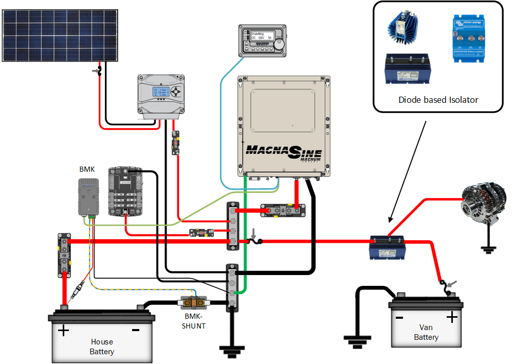
All the above solutions suffer from the same problem, they fail to protect the van or host vehicles electrical system. Once, tied together there is no way for these solutions to know the house system may be overloading the vehicles electrical system. Depending on your house current needs while driving, depth of discharge of your battery and alternator output the current draw may drop the voltage too low for some sensitive equipment.

My rig has the Starcool III Air-conditioning option, if am running that with the blower on high, my computer infotainment system, refrigerator, and trying to charge a battery from 50% DOD, my alternator will not supply enough amps at idle. Since the current draw doesn’t change the result will be a drop-in voltage from the alternator. Can it be managed yes, I could get a bigger alternator, turn down the air-conditioning blower or disconnect when going to idle and in this condition.

While I am not sure of the date Sure Power developed the “separator” I know that my rig was built in May of 2004 by Sportsmobile, and it had one of the first Sure Power Separators they had every installed. The “separator” brought new control to the basic solenoid. Now instead of a switch or hot circuit in “run”, the solenoid was connected by electronics monitoring the batteries. Now they could compare the voltage to set point they determined, if the voltage was above that setpoint they connected the two system together with a solenoid. They had another setpoint that they would force a disconnect if the voltage fell below that voltage. Now we had a system that could protect against overloading the vehicles charging system automatically.


Specifications
• Normal Input Voltage ----------- 9 -16 V
• Minimum Input Voltage --------- 8.5 V
• Contact life ---------------------- 50,000 Cycles
• Connect Voltage ----------------- 13.2 V @ 25°C, See note.
• Disconnect Voltage -------------- 12.8 V @ 25°C, See note.
• Quiescent Current --------------- 10- 13 mA
• Relay drive current -------------- 1.5 A
• Connect debounce ---------------4.4 s
• Disconnect debounce ------------7.2 s


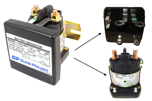
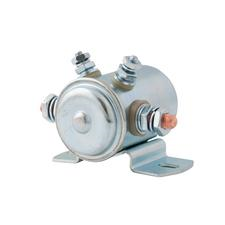
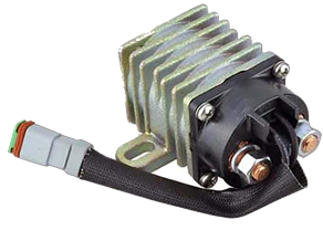
The Sure Power unit took a control unit and married it with an existing Trombetta solenoid. They have both unidirectional and bidirectional units; they also have smaller amp rated units.


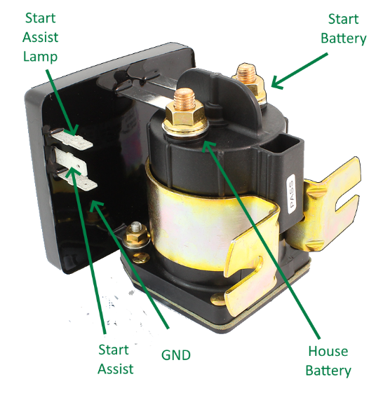
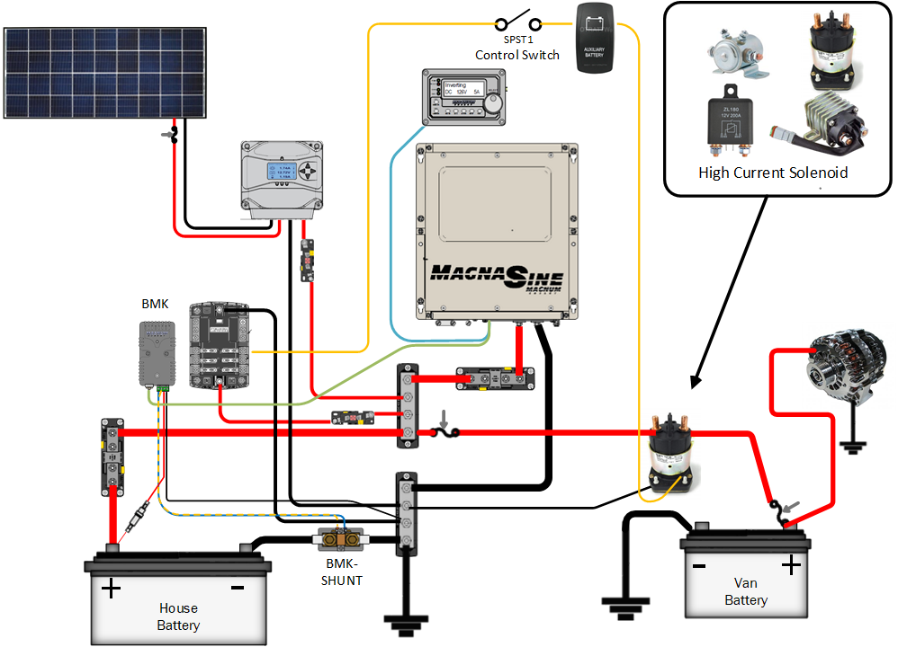
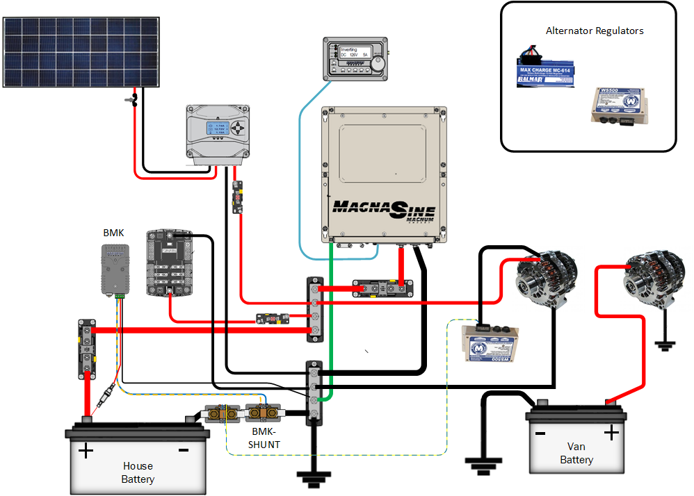
The power derived for unit comes from the house battery terminal, so we need to supply a ground connection which comes from the ground tab on the control module. The control module also attaches to the solenoid control post. All we need to connect is the two batteries systems and a ground. It is always good to put a fuse on the ground connection; this will allow some protection to the control unit. The main purpose of the control unit is to monitor the voltage levels of each battery.

The 1315-200 will activate only when either the start(main) or house(aux) battery system
exceeds 13.2 volts. The 1314-200 will activate only when the start(main) battery system exceeds 13.2 volts. If the drain on the charging system by the auxiliary or main battery bank reduces the system voltage below 12.8 volts, the “Separator” will disconnect the battery banks from each other, thus protecting the respective battery banks from excessive drain. This means if you had a heavy load and were at idle, instead of the voltage on the Van electrical system dropping below 12.8 volts, the separator will disconnect the systems. Once the voltage again exceeds 13.2 volts the separator will connect.

The Sure Power line also supports a feature they call start assist. While intentions may have been good, I generally view the start assist feature as a negative, and don’t recommend it to be hooked up to the “start circuit” but instead to momentary switch. The unit supports up 50,000 switching cycles.

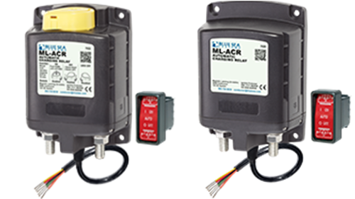
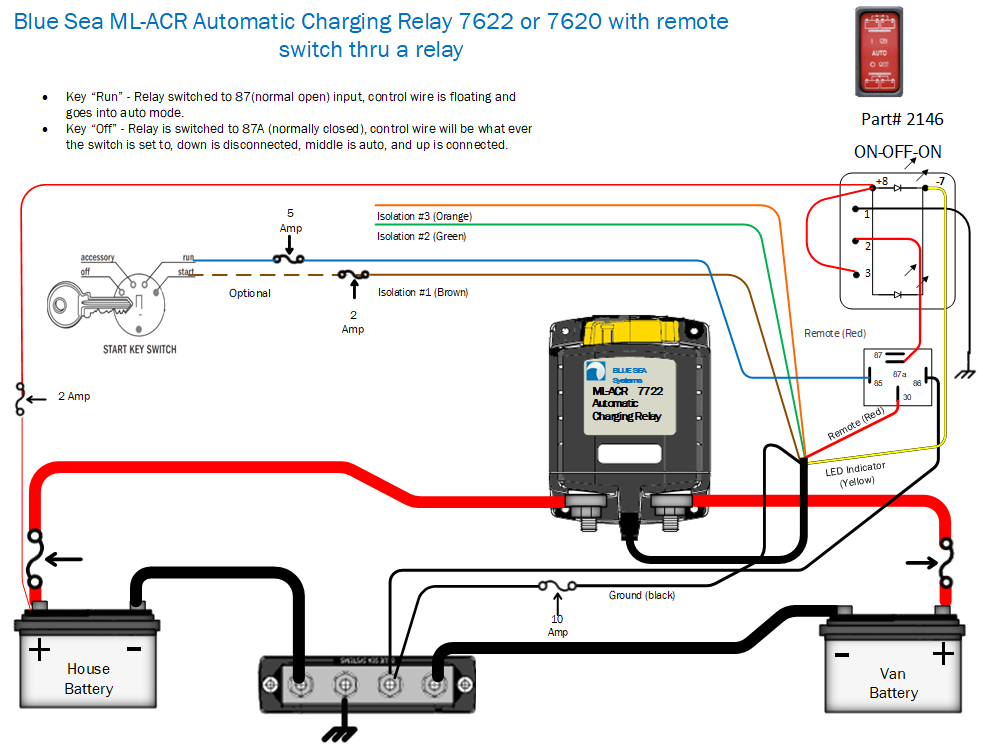
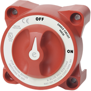
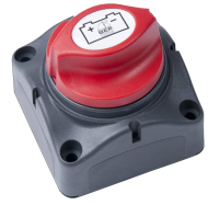
Many people started having issues with Sure Power unit, and by then Blue Sea Systems® had come out with their line of ACR or Automatic Control Relay. The Blue Sea Systems® ACR’s brought the same concepts of the Sure Power unit. Monitor the voltage and engage a relay to connect the two battery systems. The 7620 and 7622 are similar except for a manual knob provided on the 7622.


Specifications
  • Manual Control ------------------------- Yes
  • Nominal Voltage ------------------------ 12V DC
  • Cranking Rating (10 sec.) --------------2,500A DC
  • Cranking Rating (1 min.) ---------------1,100A DC
  • Intermittent Rating (5 min.) ------------700A DC
  • Continuous Rating -----------------------500A DC
    Amperage Operating Current
  • continuous@ 25°C nominal VDC -------< 13mA
    Amperage Operating Current
  • when changing state --------------------< 7.0A DC
  • Switching Cycles -------------------------100,000
  • Coil Function ---------------------------- Magnetic Latching, Auto-Releasing
  • Control Switch Included ---------------- 2146 SPDT ON-OFF-ON
  • Mounting ---------------------------------#10 or M5
  • Terminal Stud Size ---------------------- 3/8"-16 (M10)
  • Terminal Stud Length ------------------- 7/8" (22 mm)
  • Maximum Terminal Stud ---------------- Torque 140 in-lb (15.8 Nm)
  • Cable Size to Meet Ratings -------------- 4/0 AWG (120 mm²) x 2
Relay Contact Position:
  • Combine (30 sec.) ----------------------13.5V
  • Combine (90 sec.) ----------------------13.0V
  • Open Low (10 sec.)----------------------12.35V
  • Open Low (30 sec.)----------------------12.75V
  • Open High--------------------------------16.2V
While the current capacity of the ACR is larger than the SurePower units, 500-amp capability. One of the key differences is that the solenoid is a magnetic latch relay. This means that no current is being used to keep the ACR open or closed. This can important if you use solar to charge both house and start batteries, no power loss to keep solenoid active. The unit also doubles the switching cycle life to 100,000.

The 7620 & 7622 both come with a remote switch (although sportsmobile does not install them). The switch can give you manual operation and more importantly give you indication if the unit is active or not. Plus, the device will give you some diagnostic error codes.

The installation is about as simple as the Sure Power, connect the house battery and start battery, and the ground wire.

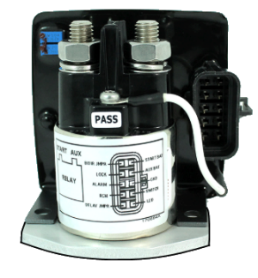
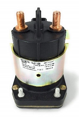
Surepower actually came out with a latching relay-based unit of their own, the Sure Power 3104 Battery Interconnect Controller, 300A


Specifications
  • Normal Input Voltage ----------------- 9-16 V
  • Minimum Input Voltage --------------- 8.5 9 V
  • Under voltage Shutdown -------------- 8.3- 9 V
  • Contact voltage drop ------------------ 0.15 V 300A resistive load.
  • Contact life ----------------------------- 50,000 Cycles 300A resistive load.
  • Connect Voltage:----------------------- 13.0 13.2 13.5 V
  • Disconnect Voltage:-------------------- 12.5 12.7 13.0 V

The 3104 uses a 300A latching relay, that supports 100,000 switching cycles. It also comes as a very configurable unit, it supports both unidirectional, bidirectional, or can be used as a LVD or low voltage disconnect. Although the Sure Power 3104 has been available since 2011, it does not seem to have caught on. I suspect in some ways that has to do with their price.

Last, but not least Trombetta, makes their own separator now, the SBS-200-003,


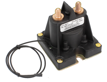
a 200A latching relay. While at this time they say you can get it in either bidirectional or unidirectional, I have found no part number difference to validate that. The Trombetta unit is an integrated unit, it supports up to 50,000 switching cycles.

All these units work pretty much on the same principle, monitor the voltages of the batteries and connect and disconnect at determined setpoints. So, they should be able to disconnect if your overall load was too high and the alternator could not keep up with the load. You may have seen one of the common specifications I have listed is switching cycles. This is because this is also a common area of failure. While some units have twice the switch cycles listed, the problem isn’t quite as simple as that. That specification is usually made with high current loads intended. In fact, a high current relay needs high current to keep the contacts clean, there is generally a minimum wetting current needed to keep the contacts from building up resistance. This is usually the number one failure of all of these units, the added resistance will rob you of available power and generate excessive heat in the units. The internal contacts of the Blue Sea Systems® 762X series can be cleaned in the field if necessary.


“Solid State” or FET based units

So, if the relay contact points can be prone to problems, why not get rid of them. Well there are some that do.
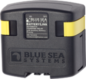
The Blue Sea Systems® 7611 “Batterylink”


Specifications
  • Continuous Rating ---------------------------- 120A
  • Intermittent Rating (5 min.)------------------ 210A
  • Maximum Cable Size -------------------------- 1/0 AWG
  • Operating Current (combine) ----------------- 175mA
  • Operating Current (open) --------------------- 15mA
  • Terminal Stud Size ---------------------------- 3/8"-16 (M10)
  • Maximum Torque ------------------------------ 140 in-lb
  • Weight ------------------------------------------1.75 lb (0.79 kg)
Relay Contact Position (12VDC )[/LIST][*] Combine (30 sec.) -----------------------------13.6VDC [*] Combine (2 min.) ------------------------------13.0VDC [*] Open Low (30 sec.) ----------------------------12.75VDC [*] Over Voltage Lockout --------------------------16.0VDC [/LIST]Auxiliary Battery Priority Optional Feature[/LIST][*] Open Low (30 sec.) ----------------------------12.25V DC[/LIST]


or 7610 “SI-Series” are commonly used to fill that need.


Specifications
  • Continuous Rating ---------------------- 120A
  • Intermittent Rating (5 min.)------------210A
  • Maximum Cable Size ------------------- 1/0 AWG
  • Operating Current (combine)----------- 175mA
  • Operating Current (open)---------------15mA
  • Terminal Stud Size ----------------------3/8"-16 (M10)
  • Terminal Stud Torque -------------------140 in-lbs (15.8 Nm)
Relay Contact Position
  • Combine (30 sec.) ----------------------13.6V DC
  • Combine (2 min.) -----------------------13.0V DC
  • Open Low (10 sec.) ---------------------12.35V DC
  • Open Low (30 sec.) ---------------------12.75V DC
  • Over Voltage Lockout -------------------16.0V DC --
  • Under Voltage Lockout ------------------9.5V DC
  • Under Voltage Reset --------------------10.0V DC


As we can see the units look identical but have some small differences. The 7611 does not have low voltage lock out and does not support start isolate. It does have an aux battery priority mode that changes the disconnect voltage to 12.25 from 12.75. The 7610 does have a low voltage lock out and supports start isolation. Both units are bidirectional.

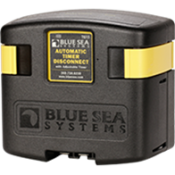
There is also another unit from Blue Sea, the 7615


Specifications
  • Nominal Voltage ------------------------------- 12V DC
  • Input Voltage Range -------------------------- 9.5–16V
  • Continuous Rating ----------------------------- 120A
  • Intermittent Rating----------------------------- 5 min. 210A
  • (Combine) Amperage Operating Current------175mA
  • (Open) Amperage Operating Current----------4mA
  • Cable Size to Meet Current Ratings------------1/0 AWG (50mm²)
  • Maximum Cable Size ---------------------------1/0 AWG (50mm²)
  • Terminal Stud Size -----------------------------3/8"-16 (M10)
  • Terminal Stud Torque --------------------------140 in-lb (15.82 Nm)
  • Time Range -------------------------------------15 Minutes – 4 Hours
    Charge Sense ON
  • Connected (3 sec) ------------------------------13.0V or greater
  • Timing (10 sec)--------------------------------- 12.75V or lower
    Low Voltage
  • Disconnected (10 sec)--------------------------Battery Voltage <
    Over Voltage
  • Disconnected(5 sec)---------------------------- 16.0V or greater


The 7615 or ATD Automatic Timer Disconnect is a multi configurable unit, it can be configured a
Timer Disconnect
• 12V signal triggers relay to connect battery power to devices. When signal is removed the timer is activated and will disconnect devices after a preset time
• Timer ranges from 15 minutes to 4 hours
Low Voltage Disconnect
• 12V signal triggers relay to connect battery power to devices.
• After 12V signal is removed, device senses low battery voltage and automatically disconnects devices.
• Low voltage setting can be used in conjunction with Timer Disconnect. Low voltage will disconnect devices prior to preset time to preserve battery power
Automatic Charging Relay
• Automatically combines two batteries when charging and isolates them when discharging.
• Single side sensing design only monitors the voltage of the start battery
• Ideal for auxiliary batteries that are AGM or significantly larger than the start battery
Solenoid
• 12V signal will connect or disconnect relay without any time delay

This unit will operate as a unidirectional ACR, the connect voltage is 13.0 V for (3 sec) and disconnect voltage is 12.75 V. The unit can still be used as a solenoid switch in this configuration also.


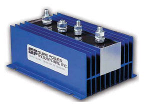
And if you need more power, you can look at Perfect Switch, they also have a programmable relay.


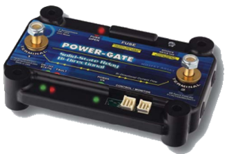
As with the PerfectSwicth isolator can be purchase in 50 to 600 amps versions (50-amp increments). They have standard programable solutions in both uni and bidirectional, and for that matter could do custom programming.


Choosing an ACR

While all ACR’s or smart relays all seem to do the same things, how does one determine what to purchase? The first thing at a minimum is that the capacity of the ACR should match the output of the alternator. After that it comes down to features, so let’s go over the common features.

Combine Voltage
These units have some voltage level and time-based unit to combine the two systems together, this is a voltage level that is usually obtainable some form of a charging unit, be it alternator, shore power or solar.

Disconnect Voltage
Similarly, they have some voltage level and time-based unit to disconnect the two systems, this voltage level is usually the resting voltage of fully charged battery.

Undervoltage lockout
This is a voltage level (usually 9.6 V) that will make sure the two systems are disconnected and remain locked out until the voltage goes above this setting. The main reason for this feature is to protect the existing charging systems. Many alternators and shore-chargers are not designed to charge a dead battery. This feature has been known to catch some owners off guard. This means if you accidently drain your house battery, you can not rely the alternator to recharge. This could be worse if your shore charging option, also has a low voltage lockout.
If concerned about this feature, make sure you have the ability to override this feature. The Blue Sea System® 7622 is the same as the 7620 except it has the “manual control override knob”.

Overvoltage lockout
This is a voltage level (usually above 16 V) that will disconnect the two system, and again keep them disconnected. This is again to protect your systems.

Start isolate
This is a usually found on the Blue Sea Systems® products, by connecting this circuit to the start circuit of the vehicle, we will disconnect the two systems during starting.

Start Assist
This is the opposite of start isolate, and I will separate this into two sections
Automatic Start Assist
The start assist circuit is tied to the “start circuit” on the key switch. This will connect the two battery systems as you start the vehicle. In the authors opinion this is a bad option, this will mask a starting battery going bad, until it is usually to late. This is how Sportsmobile hooked up the original Sure Power units.

Remote Start Assist
The start assists circuit or control wire (7620/7622) is tied to a switch. In many cases this can be a momentary switch that while pushed allow the house battery to assist in starting. If using the (7620/7622) the remote switch can be turned on to implement start assist feature.

Indicator
This is usually a low side signal that is used to show that the unit is combined or not. Some units use it for diagnostic blink codes. While the (7620/7622) have LED’s in the remote switch, this line could be used with just a standard LED indicator.

Bidirectional
This refers to if the unit monitors both battery banks to see if they go above the I’m being charged voltage level. This means you can top off your starting batteries when using solar or shore power to charge your house batteries.

Unidirectional
This refers to units that are setup to automatically charge when only when the start battery system is charging with the alternator. Shore power and solar charging will house batteries will not automatically top off the starters.

I am probably in the minority, but I dislike the auto bidirectional feature of ACR’s, in my case the Blue Sea System® 7622. I am not saying I don’t want the ability to use shore or solar to top off my starting batteries, I just don’t want it to happen all the time. Here are couple of reasons:

• Mismatched batteries
if you plug in all the time and have standard lead acid batteries for starters and AGM’s for the house battery, the float of your shore charger is reducing the liquid level in your starters. Not, a huge issue if you constantly monitor the liquid level, it won’t quickly kill the battery, it can have a negative impact. Obviously solar is not on all the time so chances this would not be an issue, but in theory it could.
• Masking a bad starter
In my opinion having the battery topped off all the time mask a bad starter as much as automatic start assist mode. Again, even if you wired start isolate, you still are topping the battery off.
• Steals limited solar power
This is more of an issue with the Sure Power units but does come into play with others. When I am off grid, I want all my power to go to getting the house batteries charged.
• Longevity
A big problem with the relay-based units is the number of connection cycles. When we have solar charging during the day, we can add multiple cycles to the relay that just don’t need to be there. And here is the real kicker, they are the worst kind of cycles. Because the we are talking about limited solar current, and maybe everything is charged, we don’t see a large current being run through the relay. This helps the buildup resistance that develops on the internal contacts. This is in my opinion the number one problem with the relay-based units. Of course, if you are using one of the FET based units, this would not be an issue, no contacts to get dirty.

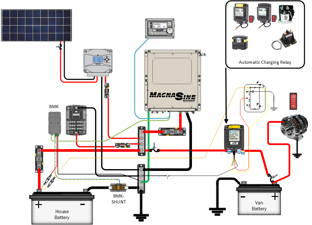
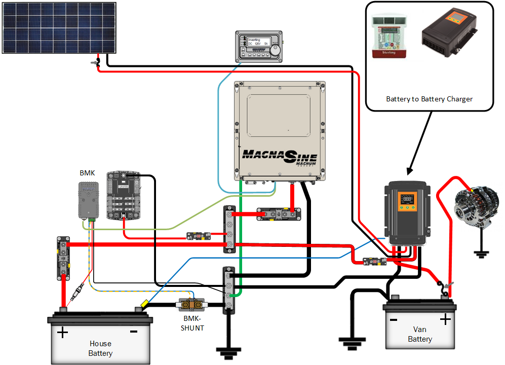
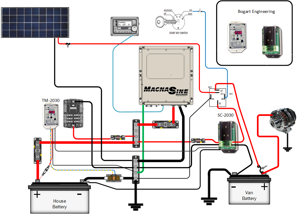
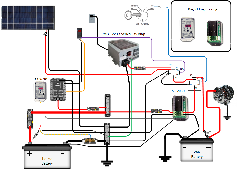
When using the Blue Sea Systems® 7622, I had the unit wired this way.


I ran the control wire from the remote switch thru a relay (87a), (30) then went to the control wire on the 7622. I grounded one side of the relay coil (85) and then ran (86) to the “run circuit” on the key switch. So, without the van running the switch works as intended, because (87a) is the normally closed input of the relay. With the van off I can switch the unit to auto, on, as I want. If I think I need to top of my starters, I can through the switch to auto. Normally I just leave it in the off position, so it keeps the batteries isolated.

Now when I start the van, the relay switches over to input (87) normally open, so now the control wire has an open input, so it is floating, this is exactly like having the switch in auto mode. My system will connect once the voltage time limit is reached and work like normal, if I had to much load for my alternator it would fall below 12.8 and disconnect the house batteries as expected. When I shut the van off, it would again default to the switch, which I usually have off. I have now turned the Blue Sea Systems® 762X into a unidirectional unit. While not for everybody this worked well for me.


Fusing
There are two places for fusing, the first would be to fuse the wires from the two battery systems. This is optional, but highly recommended. In all cases I fuse the ground connection of the unit. While fusing the ground may sound funny there is nothing wrong with it and it is part of the current path. The power for the unit is usually derived from one of the large current terminals on the unit. Any fuse there would be too large to protect the monitoring and control circuits in the unit. By placing a fuse in their ground path, we may prevent the unit from really going up in smoke. This is important and highly recommended, especially for the Sure Power units.
Scalf77 is offline   Reply With Quote
Old 07-05-2020, 06:02 AM   #5
Senior Member
 
Scalf77's Avatar
 
Join Date: May 2007
Location: Beaverton, OR
Posts: 2,478
Multistage charging
There is still one problem with all these solutions, the alternator, or specifically the charge profile of the alternator. Many times, we read about multistage charging profiles in our shore or solar chargers. The alternator does not have multiple stages. Balmar has made an external voltage regulator that turns your alternator into a multistage charger. It has multiple battery charging profiles to handle different battery types. Unfortunately, these are made traditionally for the marine alternators. It is hard to say what issues you may encounter running in one of today’s ECU controlled vehicles. I believe this solution would be inherently better suited as an option for a second isolated alternator. If your vehicle can handle an additional alternator this would be a good choice.


Ok what if you cannot handle a second alternator? Luckily, Sterling Power has come up with a solution to that problem, the Alternator to Battery Charger.

Much like the Surepower isolator went between the alternator and the two battery systems, so does the alternator to battery charger. This will allow your house battery to have a multistage charger, and still provide a standard voltage to your vehicle’s battery. Sterling has units capable to handle alternators from 80 to 400 amps and can support multiple alternators. Sterling adds features such as temperature compensation for battery charge and even can monitor alternator temperature. All units can be equipped with a remote monitor. As with all multistage chargers, Sterling has a variety of battery types to choose from. Make sure their battery type settings match the battery you are installing this on.


One of the draw backs of this system is much like that of the diode isolator, meaning that it goes between the alternator and starting battery. If something goes wrong the original system could be compromised. Sterling Power also came out with the Battery to Battery charger. Their line of B2B chargers has been expanding and they now offer one of the largest ranges (30 to 60 amps) available. They also support 12, 24,36, 48-volt systems.

The B2B is installed much like an ACR, as it goes between the start battery and house battery. The big difference is that it gives you multiple stage charging and support multiple chemistries. Many of the Sterling Power units have programable settings also, so you can precisely match your batteries parameters. They also bring along temperature compensation.


http://www.sterling-power-usa.com/li...B2BHandout.pdf


There are also other units that combine a battery to battery charger with a solar controller such as this unit from KISAE. The DMT1250 will support up to 50 amps of bulk charging.


Specifications


The battery to battery charger is getting popular, so there are many more coming on the market.

One such device while not new, but repurposed. The Bogart Engineering SC-2030
Solar charge controller can also be used as a DC to DC charger.


Of course, the SC-2030 works best when paired with the TM-2030 battery monitor.


Add a 16-volt power supply and you could have one charger for all three sources.


While the supply depicted is a three-stage charger, it also has a constant power mode.

Redarc has their own version of the one charger fits all design. The redarc manager 30 provides 30 amp charging from solar, battery and shore power. They add a built-in battery monitor (shunt based) also.


Note:
The manager 30 has a built in “stop charge” for (0°C) 32°F, as it is designed to support lithium batteries. Unfortunately, if using non-lithium batteries, you are still held to the same temperature setting. Redarc is updating their firmware in 2020 to allow non- Lithium batteries (i.e. AGM/ Gel, SLA and Calcium) to be charged down to (25°C) 13°F.


Dual Alternators

One of the problems with all these solutions is that they are based on a single alternator, or shared power source to the vehicle. The best way to have an independent source, is to add a second alternator. First, you need to find a manufacturer of a dual alternator kit, luckily there are at least some out there such as Smart Battery Charger or Nations Starters & Alternator. Add to that an external regulator such as the Balmar Max Charge MC-614 Multi-stage Voltage Regulator.


And if you wanted to take it up a notch the Wakespeed WS500 regulator adds additional features. It even communicates directly with some of the BMS systems of lithium batteries.


Up to this point I have not really talked about battery technologies. Most of these options are focused on lead acid batteries. One of the new technologies since the first post, was the use of lithium batteries. Luckily, the Battery to Battery chargers can be used to cross between the two different technologies. The second alternator option can also be used to charge a lithium battery.


Precision Circuits Inc makes the LI-BIM or Battery Isolation Manager. This is like an ACR, but it has some specific coding just for lithium batteries.


• Part Number -----------------------00-10041-261
• Relay Contacts ---------------------225 Amps Continuous
• Wire Size---- Amps Continuous---- Amps Inter(30 secs)
2/0 ------------ 225A ---------------1200A
1/0--------------200A----------------1200A
1 ----------------160A----------------600A
2 ----------------130A----------------600A
4 ----------------100A----------------600A


“The Li-BIM monitors the battery voltage of both the Lead Acid Chassis and Lithium Coach batteries over long periods of time. If it senses a charging voltage, it connects the two batteries together. If the charging system is drastically overburdened, the batteries will be isolated, however, if the Li-BIM sees a long term charging of both batteries it will allow the batteries to remain connected and allow the charging system to do its job. Once the batteries have charged for one hour, the Li-BIM will isolate the batteries to prevent overcharging, and will only reconnect the batteries for charging if one of the batteries drops to approximately 80% charge, and the other is being charged. This long term monitoring of the batteries prevents the annoying relay clicking that exists in simpler isolation modules today.

The Li-BIM does not guarantee 100% battery charge, but prevents harmful battery charge levels.”

There may also be other options that are from the battery manufacturer, or recommendations for items that work directly with your BMS system.


The products presented in this document is not complete, so do not fret if your choice is not in this shown.
Scalf77 is offline   Reply With Quote
Old 07-05-2020, 08:59 AM   #6
Senior Member
 
marret's Avatar
 
Join Date: Nov 2016
Location: FL and VA
Posts: 1,941
Garage
Awesome, thanks Greg.
__________________
Chris
2008 GMC 3500 Quigley Weldtec 4x4 Savana SMB
marret is offline   Reply With Quote
Old 07-05-2020, 11:05 AM   #7
Senior Member
 
bigriver's Avatar
 
Join Date: Feb 2014
Location: Columbia River Gorge
Posts: 649
Wow... an extremely well laid out master class on a subject I think more than a few of us have been trying to wrap our minds around. Thanks for taking the time to spell it out... much appreciated Greg.
__________________
Joe
2003 EB50 7.3L PSD Q4X4
2000 Chevy Express 3500 High Top EB37 - Sold
2003 EB30 - Sold
bigriver is offline   Reply With Quote
Old 07-05-2020, 04:46 PM   #8
Senior Member
 
Twoxentrix's Avatar
 
Join Date: Mar 2015
Location: Maryland
Posts: 3,338
Garage
Certainly will prove very useful for those looking to upgrade, or simply design for their build. Especially like the fact it was written for people like me...I was able to follow. Well done!
__________________
TwoXentrix
"AWOL"
Twoxentrix is offline   Reply With Quote
Old 07-12-2020, 12:42 PM   #9
Junior Member
 
Join Date: Oct 2017
Location: 92056
Posts: 5
Thanks for this great post!
taffeys is offline   Reply With Quote
Old 07-12-2020, 06:44 PM   #10
Senior Member
 
dhally's Avatar
 
Join Date: Sep 2009
Location: SE Washington
Posts: 1,023
Garage
I found a new device online that combines some of these functions.

https://www.thornwave.com/collections/smart-products


It is a bluetooth logging net amp hour meter, and with an external relay can work as a battery seperator. It has an onboard shunt as well. Amazing what technology can do.
__________________
---------------------
2009 E250 RB 5.4L "SilVan"
dhally is offline   Reply With Quote
Reply

Thread Tools
Display Modes

Posting Rules
You may not post new threads
You may not post replies
You may not post attachments
You may not edit your posts

BB code is On
Smilies are On
[IMG] code is On
HTML code is Off
Trackbacks are Off
Pingbacks are Off
Refbacks are Off

» Featured Campgrounds

Reviews provided by

Powered by vBadvanced CMPS v3.2.3
Disclaimer:

This website is not affiliated with or endorsed by Sportsmobile SIP or any of its affiliates. This is an independent, unofficial site.


All times are GMT -6. The time now is 09:12 PM.


Powered by vBulletin® Version 3.8.8 Beta 4
Copyright ©2000 - 2024, vBulletin Solutions, Inc.