Well, I decided that I couldnt leave well enough alone, and decided to work on more features for my RV status program for my Ford Transit. While initially the program was supposed to mainly be a way to combine rear view camera and some data from the Victron Cerbo for data access while driving. As stated, before the program runs on small MeLE PCG02 Fanless Mini PC Stick Computer.

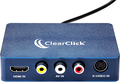
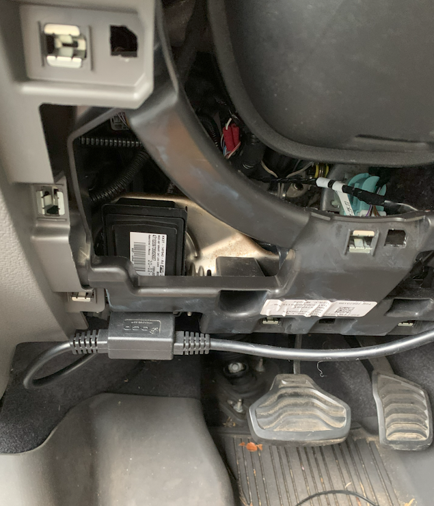
I have it mounted on the TV wall amount arm, it is not in an enclosed area, but this summer I started worrying about temperature problems, the video stream from the Mobile Mule rear camera system was getting chunky and not updating. When I got back from a summer trip, I discovered it was a thermal issue, but not with the PC Stick. It was with the USB video capture device. I purchased this ClearClick USB 3.0 to replace it. All is running well now.
I also updated the RearView mirror screen to have more data.
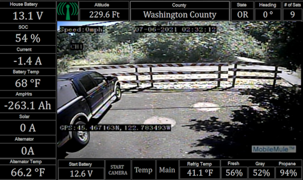
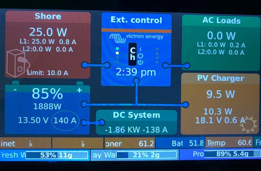
On the left I have all the pertinent battery data and the two charging sources that I may use while driving, solar and the Wakespeed controlled second alternator. Although my Battery talks to my Cerbo and my battery talks to Wakespeed, the unfortunate issue is that the Wakespeed and Cerbo dont completely talk. This made me install an additional Smartshunt to measure the alternator current.
The top row of data is for GPS data, I always like having the altitude displayed. While driving cross county this year we ran into a couple SiriusXM weather alerts, that of course go by county. My wife asked what county we were in, being that we were on I-80 in the middle of Nebraska I had no idea. This prompted me to lookup the county via an FCC government census API that can return county and state data from latitude and longitude. I fill it out with the state code, heading and number of sats. I got my data via a GPS puck connected to the Cerbo GX. The bottom row has a button row I display starter battery voltage, refrigerator temp, and the fresh, grey and propane tanks.
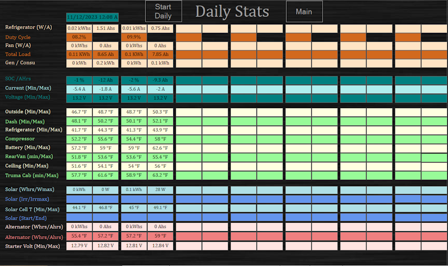
I also added a daily data screen. This screen keeps track of high low temperatures, voltage, current usage and such for the day. The screen has become pretty much an eye chart, making it kind of useless, but the data is being logged to a .csv file to be imported into excel.
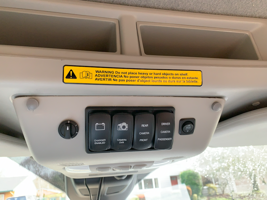
The newest screen is the charge control screen.

This allows me to set parameters for charging based on SOC, and Temperature for all my charging devices. In the following picture I show both the Multiplus II and Solar Charger charge control enabled. If the SOC falls below the setting it will turn on the charger. As you would expect the upper value would turn off the charger. This is an easy way to keep the SOC at reasonable value when sitting idle at home.
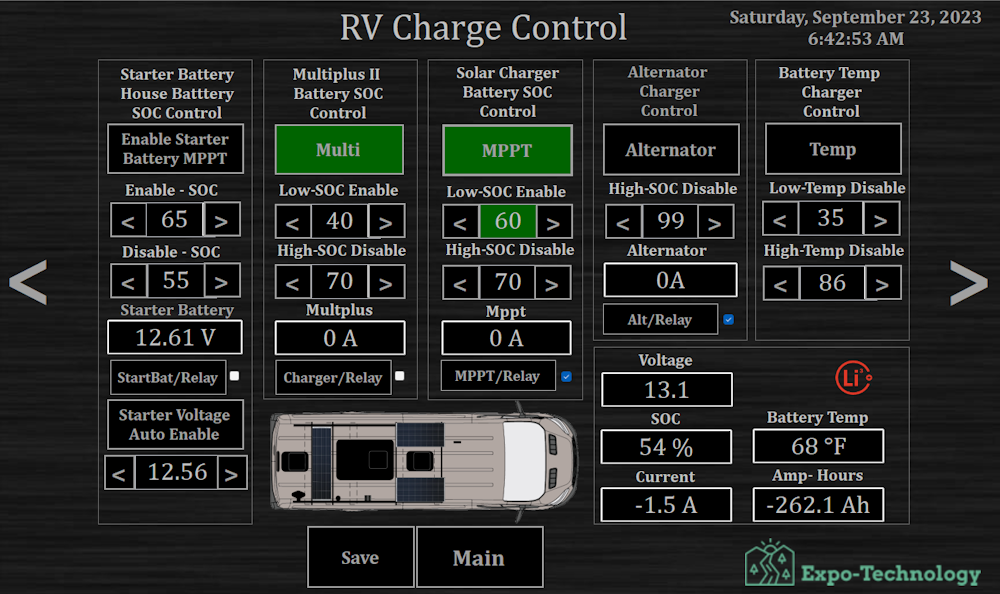
I also added temperature control, we always hear so much about the cold temperature constraints of lithium. For longevity it is also not good to charge them when they are too hot. Temperatures outside of these settings will disable chargers.
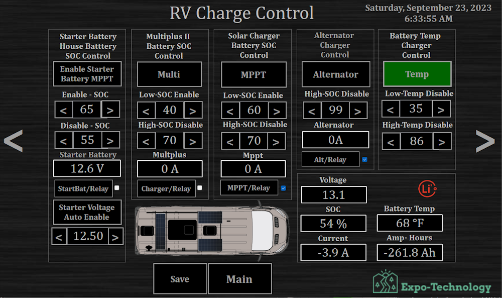
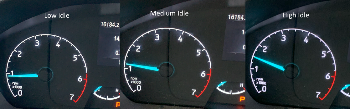
The alternator charge control can turn off my Wakespeed controlled second alternator at whatever SOC level I set it to.
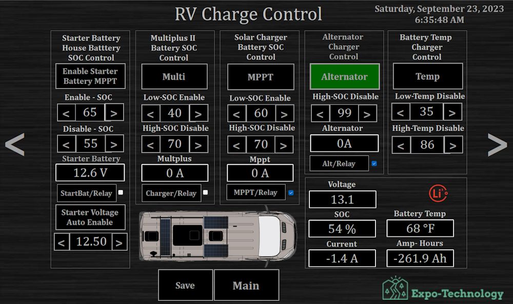
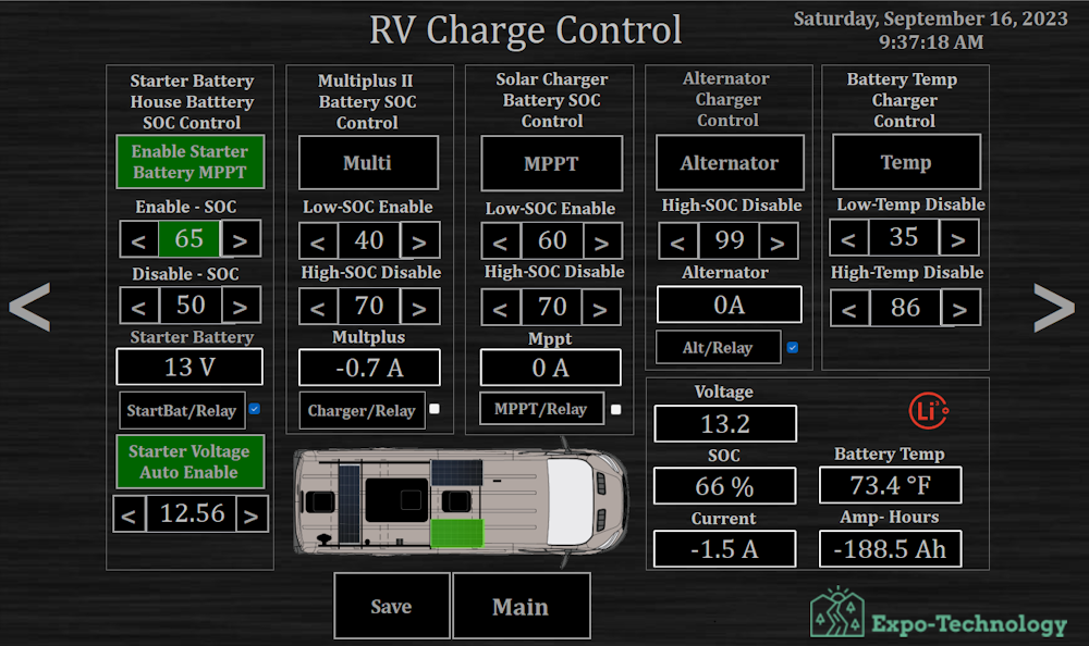
I also devoted some effort to my starter batteries. The first step is to enable it at a preset starter battery voltage. When enabled and above a set SOC it will switch one panel over to a secondary solar controller used for starter batteries. This will be switched back when the SOC falls below the preset level.
For the Charge Control Screen, I needed access to some additional relays. I chose to use one from Dingtain, their 8 Channel relay board. I chose this partly because someone had used it as a with their Victron Cerbo setup. You could see an additional 4 relays directly via Cerbo. It also has multiple access possibilities via RS485/CAN BUS/ WIFI, Ethernet, and supports multiple protocols. In my case I am using their TCP Modbus protocol. It also supports MQTT, I had mild interest in learning a new protocol, it is always good to keep the brain cells active.

This was the first additional piece of hardware that I added, that wasnt off the shelf supported via the Cerbo Path. One of my concerns about additional hardware is that it must not become an integral part of the system working. If the Relay Board could not be communicated with, full operation. This can usually be done by choosing the NC or NO path of the relay. Such as the Alternator/Relay, the main control is via a switch at the drivers console. That control (wire) goes through the NC path of the relay. I can disable the control with the relay, but I cant enable it is the control switch is not on.
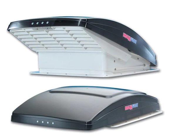
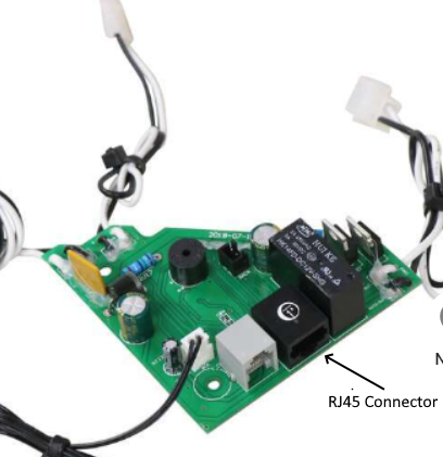
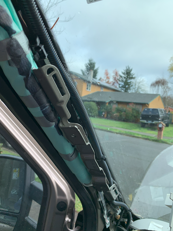
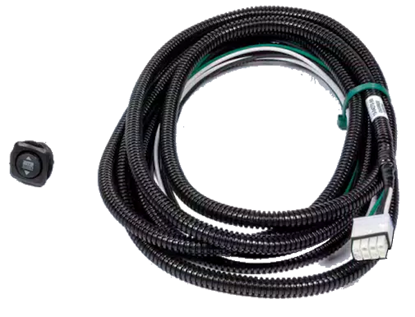
Now that I broke down the path to additional hardware, I decided to look at controlling my two MaxxAir fans. There are a few online videos or web write up on accessing the controls of the MaxxAir MaxxFan Deluxe and controlling with outside software. MaxxAir provides a easy access because of their support for a couple of wall mount remote devices. They have RJ45 and RJ25 connectors to support those.
Luckily for me someone already figured out the corresponding button controls and 8 wire pin outs of the RJ45 connector. I had previously run a low profile RJ45 cable to allow a wall remote to be installed in the future. I purchased two port RJ45 breakout board, this allows me to still use the wall remote in the future, as I dont need to hack the cable.
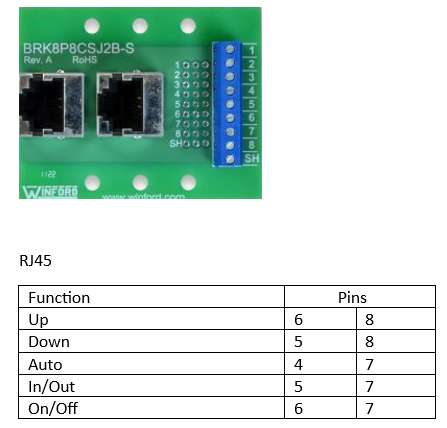
Then it simply comes down to using some network accessible relays. I had some Phidget devices around and decided to wire it up.

The next problem is feedback, how do I keep track of the state of the fan and stay in sync with the manual buttons, and remote control. In one of the videos the author speaks of the RJ25 connector and that another person had found that the white and black wire had changing voltage that changed with fan speeds. Of course, there are a couple of black and white wires, but I figured that the ones going to the fan motor were the best choice. I had to monitor both wires independently with their own voltage sensors. I first wanted to just measure the difference between the two, when I tried that I got an error on the MaxxFan.
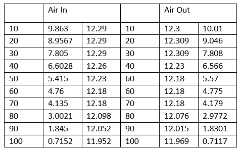
By monitoring those two wires I was able to determine the direction of the fan, the speed of the fan, and if the fan was on or off. The only state that I cant directly detect is if the fan is open or closed, and that is only when using the open/close button, no fan.
I was going to add an additional Dingitan Relay board, but when I came upon the reading the voltage for status, I already had some Phidget voltage sensors. Phidget used to be primarily USB based sensors, they fortunately saw the writing on the wall and moved to their own bus. While you can still connect to their new VNT hub to USB, they also make a Wireless or Ethernet Hub. This allows wireless connection without the use of their SBC board. So far access has been great, I am used to programing them. The best part is all access is via a single point, the Router in the van.
I access all the same things in the house or the van.
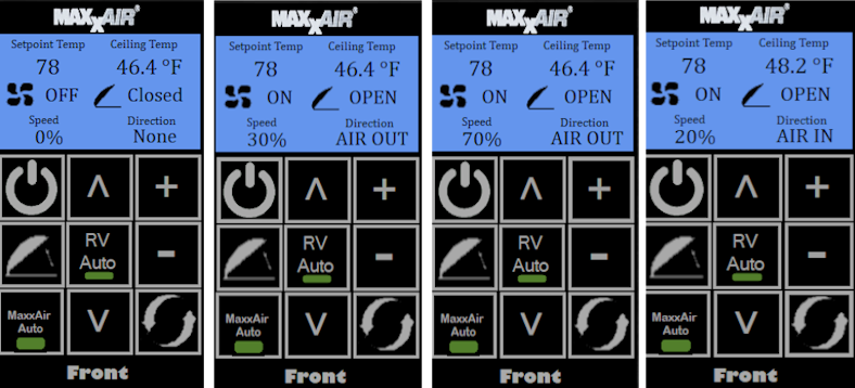
I tried to mimic the display on the MaxxAir remote, the off state, close state, speed, and direction will stay in sync with the remote. The temperature setpoint and actual temperatures are not the same, instead my own ceiling temperature sensor (which is close) and of course the setpoint will be from my program. On the outside rows you have the standard remote buttons, the middle row is for adjusting the temperature setpoint and enabling my program control. I currently have only temperature control programed. I suspect I will make that more robust such as controlling fan speed based on differential setpoint and output. Is the temp still going up lets increase speed. Do you want fans off and closed while in motion, enable an auto close feature based on engine run status and moving of location.
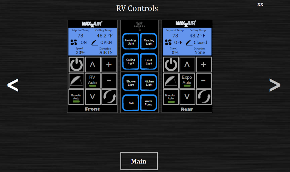
As one can see from the screen above, I have a placeholder for accessing my lighting controls from Safiery. This again should be relatively easy, the actual on/off part is, I am just working on the feedback part now. That will be a future update, that most likely will use some of the Phidget hardware. I am also looking at connecting to Ford Pass to get some of the data such as Fuel level, Lock Status, Tire Pressure, and others using their API.
I also added an systems status screen, here individual systems can be looked at individually all at once. Same data different view


 Linear Mode