I've nowhere near finished with the RV electrical system but I have completed parts of it. This post covers getting power from the starting battery to the battery separator. The separator will be located next to the house batteries under the sofa-bed. I'll be routing a wire from the positive terminal of the starting battery across the top edge of the engine compartment, through the fire wall and then across the bottom of the drivers side step well.
Since the wire will be connected directly to the battery I'll add a fuse in case there should ever be a short.

I want to have the fuse located as close to the battery as possible. Problem is there isn't much free space to work with near the battery.

After taking measurements and giving it a some thought I decided to place the fuse near the top of the engine compartment. First step is to lower this wiring bundle.

There is a space I can use between the the wiring bundle and the firewall.

Here is the fuse holder I'll be using. I cut out a poster board template of a possible mounting shield to do test fittings.

Once I cut the template to the right size transfer it to a sheet of steel laying around.

Bend the sheet as needed.

Trim the shield, drill holes, weld on a nut and paint. Then mount the fuse holder.

This is the view looking down on the edge of the hood opening. The hole on the left is where the ribbed plastic connector on the top of the wiring bundle goes through. On the right you can see the top of the screw head that secures the wiring bundle holder to the underside of this edge. The third hole from the left has a square metal piece attached on the underside. The notch cut in the top edge of the shield is to clear this metal piece.

In this photo you can see on the right were I've removed the screw for the wire bundle holder and lowered it. Put a bolt through the hole, second from the left in the above picture, that threads into the nut welded to the shield.

When I'm done both the screw for the bundle holder and the ribbed connector for the wire bundle will go through the shield to help hold it in place.

I added the yellow electrical tape to the ribbed connector since the original tape was looking weak.
With the fuse holder in place next decide where to run the wire. Being unsure sure how this would work I first used a red 6 gauge wire since it was easier to work with. After I finished I went back and redid the installation using a black 4 gauge wire. This worked out for this posting since the red wire shows up better in the photos.
First thing unscrew the fluid recovery tank from its mountings and move it forward.

Run the wire through the bundle holder along the top edge of the engine compartment.


I'm going to run the wire through the firewall in the area below the recovery tank. In the photo I already have a trouble light wedged in there.

As you can see the space is crowded.

Take your time and maneuver a drill into place. I'm drilling through the firewall. Notice the cable that passes through the firewall a couple inches below the drill.

This is the view from the other side of the firewall. I'm looking up from the area under the drivers side of the dash. You can't see it in this photo but the fuse panel is to the right. I used the cable that passes through the firewall as my guide. I triple checked that this was a good spot to go through the firewall for the power wire before drilling.

First drill a pilot hole then drill the final hole size.

Here's what I'm using as my hole size guide. I picked up this grommet assortment at Harbor Freight for a few bucks.

Find the grommet that best fits the wire I'm using. The chart under the lid shows what size hole to drill for each grommet. Just drill that sized hole.

Install the grommet.

Push through the wire.

The view inside the engine compartment before re-installing the recovery tank.

Run the power wire along side the bundle of wires that runs from under the dash along the left side of the drivers foot well and into the drivers step well.

Along the bottom of the step well and out the other side.

The wire runs from the step well to the underside of the sofa-bed and to my battery separator. Since I'll be changing my battery separator later I won't bother to describe what I currently have in place.
After running the 6 gauge wire I was sure 4 gauge wouldn't be a problem so I redid it with the larger size. Everything was the same but I did need to re-do the firewall for a larger grommet.

For the wire ends I used soldier on lugs.

Added shrink tubing to the ends.

This is a close-up of the fuse holder without the fuse.


The battery terminal allows an easy connection.

I think I'm currently using a 150 amp fuse in the holder. OK, that's it.


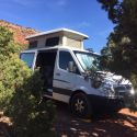
 Sportsmobile (AKA Money Pit)
 Linear Mode