|
|
 09-30-2017, 11:29 PM
|
#11
|
|
Senior Member
Join Date: Mar 2013
Posts: 4,245
|
Lots of interesting discussion about diodes and what to expect when testing them, but the original issue seemed to be that the batteries were getting overcharged. As has been mentioned, diodes cause a voltage drop, so it's unlikely they are causing a high voltage problem, and 15V is pretty high. Still, if the diodes were open circuit and not allowing the regulator to see battery voltage, the regulator would keep raising the field voltage enough that the alternator would fail, same as if you disconnected the battery cable while the engine was running. Since the batterys are seeing a high voltage though, that means the diodes are not open. Anyway, I'd measure the voltage right at the alternator, and if it stays that high, I'd call the voltage regulator highly suspect.
__________________
Arctic Traveller
KC6TNI
2001 GTRV
Advanced 4wd
Agile Ride improvement package
|

|

|
|
10-01-2017, 06:31 AM
|
#12
|
|
Senior Member
Join Date: May 2007
Location: Beaverton, OR
Posts: 2,510
|
Quote:
Originally Posted by arctictraveller

Lots of interesting discussion about diodes and what to expect when testing them, but the original issue seemed to be that the batteries were getting overcharged. As has been mentioned, diodes cause a voltage drop, so it's unlikely they are causing a high voltage problem, and 15V is pretty high. Still, if the diodes were open circuit and not allowing the regulator to see battery voltage, the regulator would keep raising the field voltage enough that the alternator would fail, same as if you disconnected the battery cable while the engine was running. Since the batterys are seeing a high voltage though, that means the diodes are not open. Anyway, I'd measure the voltage right at the alternator, and if it stays that high, I'd call the voltage regulator highly suspect.
|
Agreed, the alternator output seems to be on the high side, with the voltage regulator being the main suspect.
If the diodes are shorted you would see the alternator voltage at the batteries, (still on the high side). It does not take long to bench test a isolator, good time to clean up the terminals and such anyway.
-greg
__________________
-greg
__________________________________________________ ______________
"Goldilocks" 2020 Ford Transit High Roof Extended 3.5 EcoBoost AWD Homebuilt
|
|
|
|
|
10-01-2017, 09:01 AM
|
#13
|
|
Senior Member
Join Date: Nov 2012
Location: Brentwood, CA
Posts: 1,051
|
You shouldn't be getting 15v from anywhere in the system. I'd temporarily disconnect the isolator (to remove that variable) start the van and test the output voltage of the alternator at the alternator. I want to say spec is 13.2v-13.7v for most alternators. If alternator output is really 15v, you are likely overcharging all the batteries, boiling off the water and acid. If that's the case, it's time for a new alternator, because this one has gone bad (not uncommon).
__________________
1995 E350 7.3 Diesel, 4x4 high roof camper, UJOR 4" lift
|
|
|
|
|
10-01-2017, 09:36 AM
|
#14
|
|
Senior Member
Join Date: May 2014
Location: OrangeCounty, CA
Posts: 1,275
|
Quote:
Originally Posted by TomsBeast
You shouldn't be getting 15v from anywhere in the system. I'd temporarily disconnect the isolator (to remove that variable) start the van and test the output voltage of the alternator at the alternator. I want to say spec is 13.2v-13.7v for most alternators. If alternator output is really 15v, you are likely overcharging all the batteries, boiling off the water and acid. If that's the case, it's time for a new alternator, because this one has gone bad (not uncommon).
|
Hey good actionable stuff from everyone here.
To your comments/opinion here Tom:
Earlier in the thread I mentioned that the starter battery is reading a resting voltage of under 12 volts. So it sounds like it's indeed hosed.
You mention that there should *never* be 15V in the system. But is this always true?
To wit --- with this seemingly-now-no-good starter battery...wouldn't the voltage regulator sense this poor starter battery's deep discharge (or rather sense the starter battery's deep doomed despair....) and then "up" the alternator output accordingly? To as high as 15 volts in response to that? It does drop back down into the high 14's shortly afterward. I'll run it longer today to see where it settles after perhaps 20-30 minutes.
Going to do the continuity check on the isolator first/foremost.
Thanks guys!!! (And Bianca!!)
__________________
Mike T
___________________
'95 Ford E250 RB30 PH
|
|
|
|
|
10-01-2017, 12:27 PM
|
#15
|
|
Senior Member
Join Date: Nov 2012
Location: Brentwood, CA
Posts: 1,051
|
Quote:
Originally Posted by MountainBikeRoamer
Hey good actionable stuff from everyone here.
To your comments/opinion here Tom:
Earlier in the thread I mentioned that the starter battery is reading a resting voltage of under 12 volts. So it sounds like it's indeed hosed.
You mention that there should *never* be 15V in the system. But is this always true?
|
That's been my experience. A dead battery will still have the alternator putting out up to 14v, but more amps if the battery is almost dead.
Take a look at this youtube vid:
__________________
1995 E350 7.3 Diesel, 4x4 high roof camper, UJOR 4" lift
|
|
|
|
|
10-01-2017, 05:21 PM
|
#16
|
|
Senior Member
Join Date: May 2014
Location: OrangeCounty, CA
Posts: 1,275
|
OK --- hey, for anyone still tuned in....
I've got a heap of measurements and data from the van's electrical system.
(And a pretty big/unexpected surprise at the end of all the testing....)
I approached it with a full diagnostic combination of everything that Bianca (Glider) suggested and also what arctictraveler and Tomsbeast put forth with respect to alternator investigation. Scalf77's input and analysis has been invaluable so far as well (just realizing that the starter battery receives its voltage from the isolator has been enlightening...I thought only the house battery got it's "juice" straight from the isolator.)
Anyway, going forward...
Copy-pasting Glider's flow-chart for analysis, with my numbers/results:
a. Disconnect everything from the isolator. Check for continuity between the two output terminals on the isolator.
Continuity Check:
Zero!  Looks like the diodes (and the isolator) are still doing their job. Looks like the diodes (and the isolator) are still doing their job.

(*It might look like the wire is still connected to terminal 1, but its just the angle of the photo. It's disconnected and tucked underneath, like the other two wires.)
a.1. If you have continuity, then the terminals are shorted, and that isolator is done. End of test. Time to get a new isolator, or move to a separator.
Houston, we don't have any continuity....so we don't have a problem. Isolator is checking out ok. a.2. If you do not have continuity, proceed to Step 2.
2. Reconnect to the isolator. Measure the following voltages. Ensure that you have a quality ground for each test. Variations in your ground quality will produce unreliable results.
- Alternator output terminal to ground. 15.13 volts
- Isolator chassis battery post to ground. 14.33 volts
- Isolator house battery post to ground. 14.53 volts
- Chassis battery positive post to ground. 14.13 volts
- House battery positive post to ground. 14.53 volts
So based on this --- OBSERVATIONS:
1)
a.2. If you do not have continuity, proceed to Step 2.
2. Reconnect to the isolator. Measure the following voltages. Ensure that you have a quality ground for each test. Variations in your ground quality will produce unreliable results.
- Alternator output terminal to ground. 15.13 volts
- Isolator chassis battery post to ground. 14.33 volts
- Isolator house battery post to ground. 14.53 volts
- Chassis battery positive post to ground. 14.13 volts
- House battery positive post to ground. 14.53 volts
So based on this --- OBSERVATIONS:
1) the alternator is indeed cranking out some potentially-too-high voltage (over 15 volts).... but in terms of what the batteries actually see at their terminals, the numbers seem to be right in line with what would be considered an OK area. (Tomsbeast, that alternator analysis video you shared mentions that " between 14.2 and 14.7 volts is exactly where we want to be."
2) There appears to be a 0.2volt "line loss" between the isolator output terminal and the starter/chassis battery, which is kind of interesting (as it doesn't have to go very far....), but there seems to be zero line loss between the isolator output terminal and the house battery.
3) Both output posts see a "diode voltage drop" of alternator output vs. final isolator output of some amount, but they are both very different. The starter/chassis battery side sees a 0.8volt isolator diode drop, while the house battery side sees only 0.6volt drop. This all seems pretty much in line with what is expected of a SurePower isolator.
NEXT ---
testing without the isolator as part of the circuit....
__________________
Mike T
___________________
'95 Ford E250 RB30 PH
|
|
|
|
|
10-01-2017, 05:34 PM
|
#17
|
|
Senior Member
Join Date: May 2014
Location: OrangeCounty, CA
Posts: 1,275
|
....continued....
Okay next --- I took Tomsbeast's suggestion of disconnecting the Isolator entirely from the equation to see what the line voltages were on their own.
To do so, I unhooked all three lines from the Isolator and hard-fastened them directly to each other. (Temporarily permanently linking the two batteries in parallel from the alternator output, without any isolation circuit.)

And now, running the same experiment again, this time without an isolator to generate voltage drops (so there's two less voltages to measure this time).
- Alternator output terminal to ground: 14.38 volts
- Chassis battery positive post to ground. 14.18 volts
- House battery positive post to ground. 14.38 volts
Interesting!!!
....I really only have one observation here...which I'm struggling to find an answer to....
Without the isolator as part of the circuit..... the voltage regulator apparently responds to the lighter resistive load and drops the alternator output. The end result is that the house battery and chassis/starter battery actually see less voltage without the isolator than they do with the isolator.
Totally counter-intuitive to the conventional wisdom that there would exist a 0.7volt difference in the two readings (with isolator vs. without isolator.) The voltage regulator must be stepping up the alternator's game to overcome the additional isolator load.
(Of additional note -- the same 0.2volt line loss exists between the alternator and the starter/chassis battery, regardless of whether it is drawing directly from the alternator or if it is taking its voltage from an output terminal on the isolator.)
Weirdness.
Meanwhile...the resting voltage of the chassis/starter battery has been getting bounced all over the place this afternoon with all this testing/running the engine and alternator, but seems to be (overall) getting run up to a higher place than it started the day at. (It started the day today at 11.9 volts....was temporarily sitting at around 12.5 when I'd idle the engine for a couple minutes between readings. Ultimately, when I walked away at the end of all my testing today, and then returned 1/2 hour later, it was settling in at around 12.2 volts for the moment.)
Definitely welcome any/all analysis of today's overall test session. Thanks again for your sharp minds! Hope this "troubleshooting from the comfort of your couches" is a little bit of fun for everyone as well.
__________________
Mike T
___________________
'95 Ford E250 RB30 PH
|
|
|
|
|
10-01-2017, 06:54 PM
|
#18
|
|
Senior Member
Join Date: May 2016
Location: Pacific NW
Posts: 601
|
Mike, I like what you've done with the place!
A few thoughts:
First, let's be clear: I do not have the expertise of some of the other folks who have been chiming in on this conversation. I look for simple tests and solutions that seem to fit the bill. So--I defer to the folks who actually know what they are talking about...
That said:
1. Alternator voltage. So. The alternator kicks it up a notch when the isolator is in the equation; it behaves more normally when the isolator leaves town. Between that fact, and the age of your system, if this were my rig, I'd probably replace the isolator. Everything has a lifespan, and your isolator is probably near or at the end of its useful time. In the interest of avoiding trouble, I'd toss it and go with new.
2. Line loss on the chassis side. Clearly, it is not the length of the run. I'm assuming it is not the wire size. I'd be tempted to look at the terminals themselves, and the quality of the connection between the battery end terminal and the battery post. If I had to bet, I'd at least contemplate the possibility that there is a poor connection between the wire and the terminal (corroded wire/poor crimp) or between the terminal and the post.
Looks like everything is healthy on the house side. That's good news.
If you do decide to replace the isolator, then you will need to decide if you are going to stick with an isolator, or switch to a separator. There are pros and cons to everything, of course. If you stick with the isolator, I recommend that you call the Sure technical folks to be sure that you get the new part number.
The Sure isolators are now made by Eaton, which is owned by Cooper, which also owns Sure. Tech support is 800-845-6269. The last time I spoke with them--it has been a few years--they were very helpful. Note that some systems require a four-post isolator; some require a three-post. Yours looks like a four; be sure the replacement is the correct configuration.
Keep us posted. I'm curious to see how all of this shakes out!
__________________
OMG, the Silver Streak is Sold!
2006 SMB EB45ish.
5.4L, QuadVan 4x4
Ready to Rumble!
|
|
|
|
|
10-01-2017, 08:13 PM
|
#19
|
|
Senior Member
Join Date: Apr 2014
Location: Poughkeepsie, New York
Posts: 122
|
Your alternator regulator seems to be sensing the chassis battery at the battery. You might see an additional wire (smaller size) on the plus chassis battery terminal.
That would make the alternator track to the chassis battery rather than the alternator output.
That would be a correct implementation for a seporator.
__________________
2015 Promaster Sportsmobile
KB2ZE
Old retired IBM Engineer
|
|
|
|
|
10-02-2017, 06:05 AM
|
#20
|
|
Senior Member
Join Date: May 2007
Location: Beaverton, OR
Posts: 2,510
|
It looks like your isolator is bad, I expect the .2 volt drop is caused by a bad l connection, corroded cable or terminal connection. What year is your rig?
Here are the basic checks I usually do on an isolator. I took these pictures while working on a members van a couple of moths ago.
First I check from Terminal A (alternator) to Terminal 1 (chassis battery), if your meter has diode check, you can use it. You need to check in both directions, because of the diodes. You can see that reading changes based on the polarity of the probes.
The first pictures shows the current is flowing through the diode.

Reversing the leads we see that the diode is blocking the current in that direction.

Now we move to Terminal A (alternator) to terminal 2 (house battery) and again do the same checks.
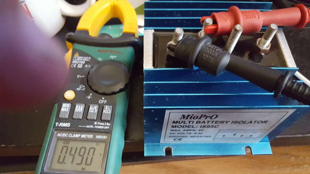

Now I check out Terminal A (alternator) to the Terminal E (excite) and provide the same checks


And the check of course that you already did, between terminal 1(chassis) and terminal 2 (house). Again I usually do this in both directions (i only have a picture showing this in one direction. Actually, this is usually the first check

hope this helps
__________________
-greg
__________________________________________________ ______________
"Goldilocks" 2020 Ford Transit High Roof Extended 3.5 EcoBoost AWD Homebuilt
|
|
|
|
|
|
 Posting Rules
|
You may not post new threads
You may not post replies
You may not post attachments
You may not edit your posts
HTML code is Off
|
|
|
|
 » Recent Threads
 |
|
|
|
|
|
|
|
|
|
|
|
|
|
|
|
|
|
|
|
|
|
|
|
|
|
|
|
|
|
|
|
|
|


 Thirsty
 Silver Streak
 Linear Mode