Okay --- went back and
extra-thoroughly re-tested the Isolator.
Realized that what one of Scalf77's earliest responses had stated truly needed to be done ---- in order to
fully, properly assess the isolator --- was that there needed to be
not just a test for continuity across the isolator's terminals --- there also needed to be proper testing to see that
there was only one-way continuity across those terminals. In short (hah, electrical pun....), the isolator's internal diodes needed to be tested to make sure they were properly behaving....Diode-ey.
(Diodes should only allow current to flow through them in
one direction.)
So.
Got back out the trusty Craftsman Multimeter....and set it up for Diode Test/Check parameters.
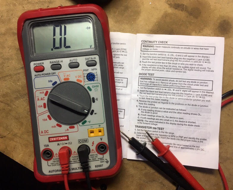
The instructions are
remarkably straightforward for testing the proper operation of a diode:
1) If the diode is good, you'll measure
current flowing across it in one direction, but not the other.
2) If the diode is bad, you'll either
a) measure current going in both directions (shorted out diode) or b)
measure zero current going in either direction (burned out diode.)
 So anyway....
.....on to the testing procedure for the Sure Power isolator that
Scalf77 presented earlier.
(My results indicated in green.)
--------------------------------------------------------
INSTRUCTIONS FOR TESTING A SURE POWER ISOLATOR WITH OHMMETER*:
1. Remove all wires from the isolator.
2. Using a needle movement ohmmeter RX-1 scale or a digital ohmmeter diode scale, hold the Red* probe on the terminal "A" and with
the Black* probe touch terminal #1 and #2, and the "E" terminal for 3A isolators (group 2), and the "R" terminal for (group 3) isolators.
A good isolator will show a current flow from "A" to #1, #2 and "R", and no current flow to "E".
SUCCESS:
Current flow from A to #1: display shows 0.380
Current flow from A to #2: display also shows 0.380
3. Next, hold the Black* probe on the "A" and with the Red* probe touch terminal #1 and #2 (terminal "E" and "R", if used). A good
isolator will allow no current flow from "A" to #1, #2 or "R" and will show current flow from "E" to "A".
SUCCESS:
Current flow from A to #1: ZERO
Current flow from A to #2: also ZERO
Current flow from E to A: YES -- display shows 0.395
4. Hold one probe on the aluminum heat sink, being sure there is contact by scratching through the protective coating. Then touch
with the other probe, terminals "A", #1, #2 (the "E" terminal for 3A isolators [group 2] , the "R" terminal for group 3 isolators). A
good isolator will show no current flow.
SUCCESS:
Current flow from aluminum case to A: ZERO
Current flow from aluminum case to #1: ZERO
Current flow from aluminum case to #1: ZERO
5. Colored terminal indicates "E" post on group 2 isolators and "R" terminal on most group 3 isolators.
*On some import ohmmeters, the red and black probes are reversed for these tests.
**If using a digital ohmmeter, a diode scale MUST be used.
--------------------------------------------------------
Conclusion:
As far as I can see,
this Sure Power isolator is still 100% functional and within spec.
(*Scalf77 and others, it would be great if you weighed in and confirmed this?)
 At this point, it seems that the following two priorites stand out:
1)
At this point, it seems that the following two priorites stand out:
1) attempt to address/remedy the 0.2 volt "line loss" between the isolator and the starter/chassis battery (install a new run of adequate gauge positive wire between the output terminal of the isolator and the positive terminal of the starter battery)
and
2) replace the starter/chassis battery (as its resting voltage of between 11.9 and 12.0 isn't very encouraging.)
Still.....really need to figure out
why the starter/chassis battery seemingly overcharged/boiled.
Has adequate investigation of the the alternator end of this equation still been neglected? So far,
it seems that the alternator (and its associated voltage regulator) have been performing exactly as they should do --- apart from a brief surge to 15 volts for a minute after starting the engine a few days ago, it has been
supplying a correct 14.2 to 14.7 volts to the starter battery, whether there is an isolator in the circuit or not.
Boiling/ruining batteries gets expensive (and old) pretty fast.


 Thirsty

 Sportsmobile (AKA Money Pit)


 Linear Mode