Battery Isolators, Separators, Switches & More (updated 2020)
It has been a while since I first posted this thread, so I thought it might be a good time to update. The primary reason is the technology itself; we tend to have more options out there today than there was before. Also, my own knowledge and usage model has progressed and changed over the years as have some of the pros and cons of possible solutions.
The first and most important thing to remember is that there really is no one perfect solution, depending on our electrical needs and/or vehicle one solution may be better than the other. What works for camper A may not be the best solution for camper B. The second thing is that these solutions are still dependent on the alternator for power.
Alternators are typically referred to by their max ratings, I have a 140-amp alternator, or I upgraded to a 250-amp alternator. What does that really mean? Luckily, there are standards for measurements. Both ISO 8854 and SAE J 56, alternator testing and labeling standards indicate that the rated output of an alternator is the amount of current that it can produce at 6,000 RPM. They also refer to idle speed, which really depends on the standard, but usually can be referenced to 1,500 RPM. This is referring alternator shaft rotation not engine RPM. Typical labeling of an alternator requires a format of IL / IRA VTV, where IL is the low, or idle, amperage output, IR is the rated amperage output, and VT is the test voltage.
A common example is 50/120A 13.5. Here 50 refers to the current provided at idle or the low test speed. The 120 refers to the rated test speed, this is generally the number used for the rated output, as in I have a 140-amp alternator. And then we have VT, which is the voltage that the alternator was held at during the test. The actual rating will go up or down based on the voltage output setting of the alternator in your vehicle.
The important thing to remember is that the output of your alternator is load dependent. Just because it has a rating of 140-amps does not mean that it is always putting out 140 amps (or 50 amps at idle). This is controlled by another important part of the charging system, the voltage regulator.
The regulator is usually internal to the alternator, but on some vehicles it is external. Even if the regulator is internal, the control of that regulator may be back at the PCM or ECU. As with anything controlling the output of the alternator with a computer can be both simpler and more complicated. Still the basic principle is more load on the alternator drops the voltage, the alternator must increase its output to keep it at the voltage setpoint. The inverse is true, with a reduced load the alternator reduces the current, so that the voltage does not go too high.
Then of course a lot will depend on your rig, we can take the E350 in a V10, and it is relatively tolerant to lower voltage. if you have the 6.0 diesel you have components like the FICM that is much less tolerant to lower voltages. We also have housekeeping load on the RV side. Some rigs may have a very low load for their housekeeping footprint, while others may have Starcool or run their inverter while driving. Typically, in my rig if I have the battery below 70%, Starcool (rear air conditioning) fan on high and running onboard entertainment systems the housekeeping load is too high for the alternator at idle. Turning the Starcool blower to low would alleviate the potential problem.
Switches
Let us go back to the simple battery switch. We have a hard switch that you can purchase for the possible current needs you have. All this switch does is put the starting battery in parallel with your house battery system. We simply close the switch when the van is running and allow our existing alternator system to charge the house battery and housekeeping loads.
Pico 5575pt Master Batt Isolator Switch
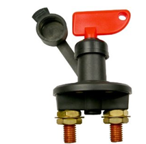
- 2 Position On-Off with Removable Key
- 3/8" x 3/4" Length Studs, 4 3/16" Mounting Holes in Base
- 12 Volt 350 AMP DC Continual,
- 12 Volt 500 AMP DC Momentary (10 Seconds)
Blue Sea m-Series Mini On-Off Battery Switch with Knob Red #6006
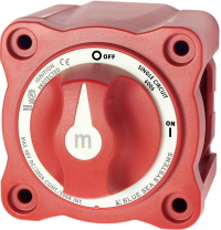
- Single Circuit On-Off
- Maximum Voltage -------------- 48V DC
- Continuous Rating -------------- 300A
- Intermittent Rating -------------500A (5 min)
- Cranking Rating 30 sec. --------900A
- Cable Size to Meet Ratings --- --4/0 AWG (120mm²)
Blue Sea e-Series On-Off Battery Switch #9003e
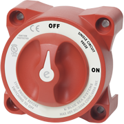
- Single Circuit ON-OFF
- Maximum Voltage -------------- 48V DC
- Continuous Rating -------------- 350A
- Intermittent Rating -------------600A (5 min)
- Cranking Rating 30 sec. --------1200A
- Cable Size to Meet Ratings------4/0 AWG (120mm²)
Marinco Contour Battery Master Switch #701
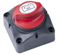
- Single Circuit On-Off
- Maximum Voltage ------------- 48V DC
- Continuous Rating ------------- 275A
- Intermittent Rating ------------ 455A (5 min)
- Cranking Rating 30 sec. ------- 1250A
- Cable Size to Meet Ratings-----1/0 AWG (120mm²)
While all these switches can do the job, some might meet the needs of your rig better than others, notice the Blue Sea Systems® & Perko® switches have a Cranking Rating 30 sec, which could be important if you plan on using your house battery for emergency starting. You should also notice one other important part of their specification, Cable size to meet ratings 4/0 and the note * Reducing cable sizes will reduce current ratings. If you have question on the reduced ratings it would be best to contact Blue Sea Systems® directly for feedback.

Since the switch just puts the two electrical systems in parallel, one could use the same switch to charge both the house battery and van battery from either shore power charger or solar charger. But again, it is a manual switch.
While this is a simple solution it has some drawbacks, the primary is that you need to manually turn the switch. So, you need to remember the open or close the switch. It is also difficult to position the switch, as it must carry a fairly large size wire but still be accessible.


 Threaded Mode