Since this question came up in a different thread, I thought I would answer it in its own thread instead of it getting buried in another but interesting
thread.
Letís look at the effects of shading on our solar panels, and ultimately what that means to how we choose our system, position both our panels on the van and other equipment on top of the van. I will try to keep it simple and try not get caught up in the technical issues (Reverse bias, forward bias, negative charge, etc.).
The panel below is made up of 36 Individual Solar Cells (36 Cell Panel), in this case it is 4 rows of 9 cells. Some of the older panels may be 32 (4 x8), there are also larger panels such as 60 cells (6 x 10) and 72 cells (6 X12). I will use the 36-cell panel for most of this discussion, but most of the data will apply to other panels.
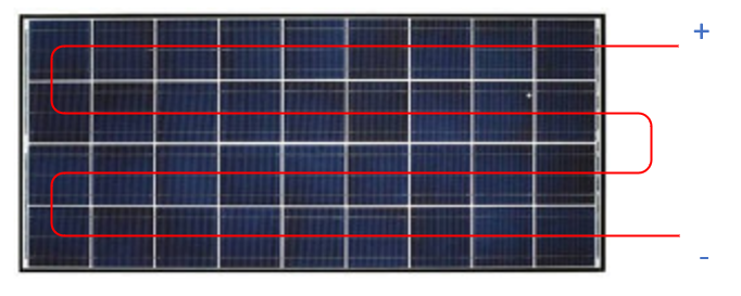
The cells are connected to each other in series, each cell puts out about 0.668 volts, so when connected we gat 36 X 0.668 = 24.06 which is the Voc of the panel. Each cell also can provide 9.77 Amps which is Isc. A shaded cell will drop both voltage and current it produces dependent on the amount of shading. The impact of a shaded cell goes farther than just the shaded cell. The cells are attached in series, and the lower current output of the shaded cell will limit the output of the other cells connected in series. This is much like a blockage in a water pipe, will limit the flow of water in the whole pipe. So, if one cell is shaded and puts out only 2 amps than all the cells in series will put out only 2 amps.
The problem with this is that the power created from the other nonshaded cells, must go somewhere. Unfortunately, because some of those technical issues (reverse bias) we see the shaded cell now becoming a consumer of energy, which creates hot spots. So not only does shading rob our overall system of power output, it can cause hotspots that can affect the lifespan of our panels.
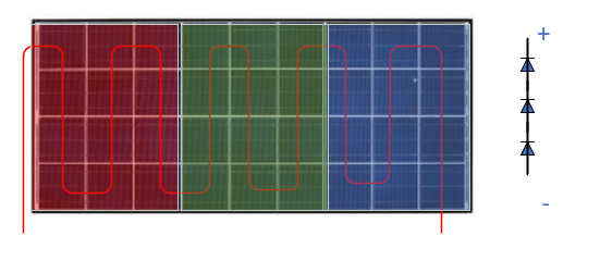
Luckily the panel manufacturers put in some protection to offset the problem of shading. These protections are really to prevent hotspots, rather than provide better output. As we said the single shaded cell restricts the current of all the other cells in series, that current must go somewhere and generally its get dissipated by the restricted cell causing hot spots. This is where the bypass diode comes into play, when a diode is placed in parallel with the offending cell (in the opposite direction) the diode will create a short circuit around the cell letting that backed up power to go by. This of course limits the hotspot but does remove that cell from the capabilities of the panel. This sounds great if every cell has a bypass diode, then why should we worry. Well, because the diodes cost money, and it becomes a tradeoff of protection to cost. There is a least one solar cell manufacturer that has a built-in bypass diode, most do not and typically we will find them installed in the junction box.
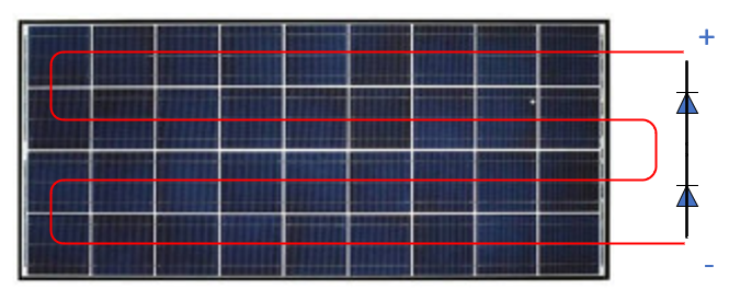
A very typical layout would be to have 2 bypass diodes for a 36-cell panel. That covers 18 cells with each diode. 60 cell panels usually have 3 bypass diodes across 20 cells.
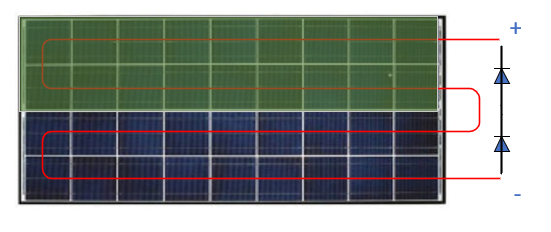
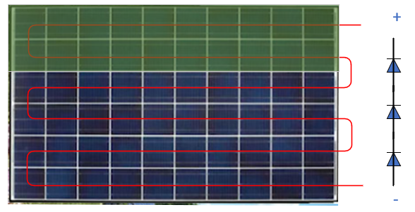
Now what does all this have to do with the panels on our roof? Well first, we eliminate any shading in our layout. Many times, we have seen where the rack, vent or equipment box was shading a panel from the get go. Where you may run into some shading you can try to minimize it. In the following examples both have heavy shading of 4 Cells, but the resulting output of the panel would be completely different. In one case the shaded cells are across cells contained in both bypass diode circuits. It would essentially put out no power.
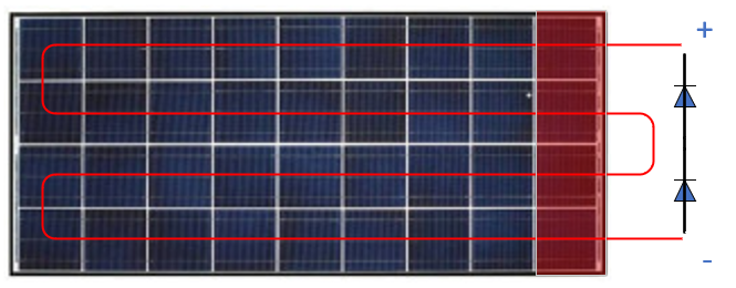
The second example shows the four shaded cells contained in one bypass diode circuit. This would allow at least half of the panel to produce power.
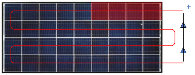
Now, before you go start rearranging your panels, letís dive a little deeper. The first thing we need to look at is what kind of controller do you have? If you have a PWM controller you should stay in your seat. Imagine the above panel being an 18-volt panel, if we bypassed half the cells we could only expect half the voltage or 9 volts. This means the PWM controller would not have enough voltage to operate. If you have a MPPT controller, you could still pull some power out of this panel.
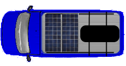
An example of tweaking the layout can be seen below, same two panels but with different panel orientation. In the top layout we can see some possible shading issues caused by the storage box. This is limited to some degree by the orientation of the panels. Shading by the box will only encroach on one of the two panels, and at worst one group of bypassed cells.
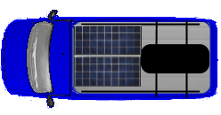
In the example below, the box now is encroaching even more, guaranteeing more shading. The real problem is now we shade across both panels.
The next layout is a classic problem, bars going over our panels. This example is somewhat exaggerated but its always good to check the shadow of bars, lights etc.
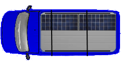
Another thing to consider is roof vents, please check the shadow when the vent is in the most common up position and make sure where it is casting its shadow.
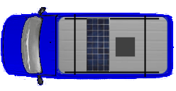
In general, just use some common sense, most of our shading issues are going to come from other site issues. A disconnect switch may be useful, if you need to store items over the tops of your panels for various trips.
A couple of extra notes, as the solar cells seem to get more efficient year after year I expect that you will start seeing more bypass diodes, obviously the more current a cell can produce will impact the number of cells that can be protected by a single bypass diode. The number of diodes is not even listed on the spec sheets of most panels, you may have to call the manufacturer. My panels have three bypass diodes across 12 cells each instead of the 2x18 configuration
A couple of good YouTube videos to explain the technical aspects of shading can be found here:
hope this helps a little.
-greg