Looking for some input on my power plan for my DIY build. Nothing to major (no shore power, inverter etc) Just basic DC to DC with an option for solar. My plan for the stereo is to run the external amp for front speaker and sub only when the ignition is on.
For the rear speakers running of the headunit, my plan is to take the factory switched power and run it through the NC side (terminal 87a) of a five pin relay, and a leg from the house fuse block through the NO side (terminal 87) and have a switch to trigger the relay located near my power distribution in the rear of the van. That way I have the ability to remotely switch on the headunit and toggle power sources. (Might need a diode between the factory power source and the headunit?)
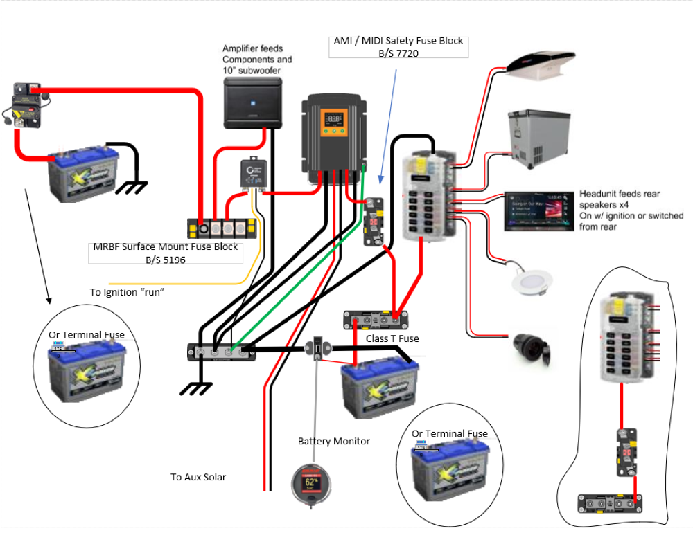
I apologize in advance for my crude drawing, I am not a Vizio/CAD user, Google Draw was the best I could come up with.
FYI, the different line weights from the power connections indicate the wire gauge. 0awg, 4awg and 12awg respectively. Thanks in advance for any input.
I made a couple of changes with multiple options. I prefer the terminal fuse instead of the circuit breaker, but it is a personal choice. The Terminal Bus Bar is a good way to distribute power, and would take place of bus bar and individual fusing.
I added a cut-off relay for the start battery input of the KISAE DMT12x0, you do not need the ignition option on the KISAE.
You should fuse the house battery, and you can't do any better than a Class T fuse. You did not mention what size house battery you are going for , or what the actual distances were from components. So don't read much into the weight of my wire sizes, but those would need to be calculated and fused properly.
If you are using the battery shown in your diagram you could probably use a terminal fuse here also. Also with the smaller battery shown, I would limit the charge output of the KISAE for the battery size.
Oh, and I added a Balmar SG200 Battery Monitor.
Feel free to ask more questions here or in a PM.
-greg
__________________
-greg
__________________________________________________ ______________
"Goldilocks" 2020 Ford Transit High Roof Extended 3.5 EcoBoost AWD Homebuilt
I made a couple of changes with multiple options. I prefer the terminal fuse instead of the circuit breaker, but it is a personal choice. The Terminal Bus Bar is a good way to distribute power, and would take place of bus bar and individual fusing.
I added a cut-off relay for the start battery input of the KISAE DMT12x0, you do not need the ignition option on the KISAE.
You should fuse the house battery, and you can't do any better than a Class T fuse. You did not mention what size house battery you are going for , or what the actual distances were from components. So don't read much into the weight of my wire sizes, but those would need to be calculated and fused properly.
If you are using the battery shown in your diagram you could probably use a terminal fuse here also. Also with the smaller battery shown, I would limit the charge output of the KISAE for the battery size.
Oh, and I added a Balmar SG200 Battery Monitor.
Feel free to ask more questions here or in a PM.
-greg
Awesome info, thanks!
A little more info on what I'm working with:
House battery-X2 100ah AGM (may add a 2nd down the road depending on need)
Charger- Kisae DMT1250 (intentionally oversized for future battery expansion)
I used a wire gauge chart from Blue Sea to calculate wire sizes. The amplifier I'm using requires a 60a fuse and the Kisae a 70a running at full 50a output capacity. Combined max draw of 150a draw with a distance of ~15 from battery to buss bar, chart calls for 0awg, stepping down to 4awg to feed the amp and DMT. 4awg again out of the DMT to the house battery and same from battery back to fuse block.
I like the idea of combining the the fuse and bus bar and the terminal fuses at the batteries.
What's the ignition switched piece between the fuse block and Kisae? Looks like some type of ACR.
Definitely do the bigger Kisae...long story, but it's a better unit than the 1230 and DOES work with their remote display panel should you need that (I've posted elsewhere about that).
I also added the relay Greg suggested. His excellent thread on the electrical setup explains that, and that's reason enough to install it. But I also like having some cutoff between the starter/alternator system and the house system, and it's a nice semi-auto way to do that.
You might not want or need the shunt for a battery monitor on the negative side (Victron also makes one that simplifies the wiring over my old Link 10 eg). But for future use you might want to have something there so you could swap one in at a later date. Or maybe even just a shunt and basic ammeter.
I've also got a battery shutoff for the house batteries. The Kisae has an on/off switch, but it's devilishly hard to reach, and having a way to cut all power is really handy at times.
__________________
2001 Ford E250 Sportsmobile with Salem-Kroger 4x4 conversion
Negative bus bar chassis ground. Does this need to run all the way back to the start battery, or can I just attach it to the frame?
Both my batteries are located on the outside of the van, meaning I'll have a fair amount of connections running in and out of the van body. Is there a good product to support multiple cables or should I plan on just using a gland per cable for penetrating the body?
Negative bus bar chassis ground. Does this need to run all the way back to the start battery, or can I just attach it to the frame?
Your choice....I ran a ground wire between the start battery and the house batteries, but frame ground works. I ran lots of ground wires back to fuse boxes, etc.
Quote:
Originally Posted by ibike
Both my batteries are located on the outside of the van, meaning I'll have a fair amount of connections running in and out of the van body. Is there a good product to support multiple cables or should I plan on just using a gland per cable for penetrating the body?
Blue Sea makes red and black bulkhead terminal posts....good choice.....
My floor build-up was too thick for those so I fabbed my own longer versions.
The ideal case is 1 wire 1 gland, I sometimes wrap smaller wires in some butyl around the wires to make sure there is a good seal. I drill a hole through the sub-floor large enough for the outsider diameter of the gland. Then drill the hole for the tread size.
You should run a ground from start bat to frame the same size as start positive to fuse bar. And of course from frame to ground bus bar. If you don't go wire from Start ground to ground bus bar.
-greg
__________________
-greg
__________________________________________________ ______________
"Goldilocks" 2020 Ford Transit High Roof Extended 3.5 EcoBoost AWD Homebuilt
The ideal case is 1 wire 1 gland, I sometimes wrap smaller wires in some butyl around the wires to make sure there is a good seal. I drill a hole through the sub-floor large enough for the outsider diameter of the gland. Then drill the hole for the tread size.
You should run a ground from start bat to frame the same size as start positive to fuse bar. And of course from frame to ground bus bar. If you don't go wire from Start ground to ground bus bar.
-greg
Thanks for the clarification. Any thoughts on one of these multi cable glands? I'm planning on building a box around the rear passenger wheel well to house all the electrical components, so I thought I might mount one of these on the frame side of the body and bring all my cabling up through the rocker panel cavity and out through one of the holes from the factory stamping inside the van.


 PhoTo
PhoTo

 Linear Mode