|
|
 03-23-2024, 09:44 PM
|
#11
|
|
Member
Join Date: May 2017
Posts: 64
|
Given those diagrams, I think you must be right and I was upside down in the way I was looking at the connections.
I'm still not sure what the relay does exactly. Does it make sense that, absent of an electrical activation, the relay connects pin 30 to pin 87 (which doesn't connect to anything), and the orange wire is connected to the door-ajar switch(s) so that when a door is open that sends power via the orange wire to the relay which then switches the connection to be from 30 to 87a rather than the default 87? Assuming one of the red wires to pin 30 is connected to the battery, it would then cause power to flow from the battery to the controllers.
|

|

|
|
03-24-2024, 05:50 AM
|
#12
|
|
Senior Member
Join Date: May 2007
Location: Beaverton, OR
Posts: 2,506
|
Being that it looks like it is connected to the NC or normally connected path, you would be correct, without the relay energized the path between 87a is already present. When the relay is energized (positive voltage) on orange wire and ground, then it would disconnect the path. This is still acting just like a switch, I suspect just for power by the size of the wires. If it is power then it would be there all the time, except when the relay was activated.
I don't see it being a polarity changer the way it is wired (although that was a good idea)
I would try to track down the orange wire as it is most likely the control wire, although you could control the ground side.
__________________
-greg
__________________________________________________ ______________
"Goldilocks" 2020 Ford Transit High Roof Extended 3.5 EcoBoost AWD Homebuilt
|
|
|
|
|
03-24-2024, 08:10 AM
|
#13
|
|
Member
Join Date: May 2017
Posts: 64
|
All this still has me confused wondering what function the relay plays in the process of extending and retracting the steps, and how it accomplishes that. I'm going to get back out to the van later today or tomorrow and do a better job of tracing the various wires. That should help.
|
|
|
|
|
03-24-2024, 09:02 AM
|
#14
|
|
Senior Member
Join Date: May 2007
Location: Beaverton, OR
Posts: 2,506
|
I agree, the best I can come up with at this time, is there is some kind of override switch, that disconnects power for some reason. Maybe attached to engine "run" so that power will be disconnected when the van is running.
Tracing the wires should further should help
__________________
-greg
__________________________________________________ ______________
"Goldilocks" 2020 Ford Transit High Roof Extended 3.5 EcoBoost AWD Homebuilt
|
|
|
|
|
03-24-2024, 12:02 PM
|
#15
|
|
Senior Member
Join Date: Mar 2023
Posts: 147
|
OK so the plot thickens as they say, combined by the technician at AMP's lack of product knowledge.
Reading the instructions for the kit part number provided, this kit is for PASSENGER SIDE ONLY. There are independent triggers for the slider and frong passenger door. The trigger wires are different colors that the purple/purple black that is standard for AMP STA controllers but good news they are identified in the documentation and the troubleshooting steps are the same (ground the trigger, see if the steps move, proceed based on results)
(instructions for the single sided kit PN provided by the OP)
https://static.thiecommerce.com/asse...67ea87e3f0.pdf
The reason for two controllers is you likely have two kits installed on your vehicle, one for the drivers side and one for the passenger side, each with their own controllers, which you already surmiesed. I can't find documentation for this kit so your guess is as good as mine to the OEM part numbers.
The standard dual-sided AMP step kit does use the purple trigger wires as previously described and includes a little module that sits out on the CAN and intercepts the door open signals. It also uses a single STA controller.
(Instructions for the dual side, single controller kit with CAN intercept module)
https://static.thiecommerce.com/asse...1c188a8f2d.pdf
Anyway long story short sounds like this is a real hodge-podge of parts, its fairly simple to troubleshoot but probably not going to be a black-and-white path considering the situation.
In theory a guy could un****ulate this if you can source the CAN module and wiring harness from the dual side kit, remove the relay and one controller, follow the wiring instructions for the dual side kit, and you would keep full functionality and remove failure points. I have heard AMP is tricky on spares and the instructions do not have part numbers in their instructions.
|
|
|
|
|
03-24-2024, 05:11 PM
|
#16
|
|
Member
Join Date: May 2017
Posts: 64
|
Big_ern_101 and Greg, I have comments regarding your most recent posts but first let say that I have fixed the problem. Here's how.
I got my van out of storage today and started to troubleshoot the problem some more. My first order of business was to verify the wiring on the relay and to trace those wires to their connections. Among other things, I found that the orange wire from pin 86 on the relay and a red wire on pin 30 got bundled with two purple wires, one from each controller, and then passed under the edge of the driver seat base, along the side of the driver side foot well and then up under the dash. They ended up with some other wires also bundled with them along the way. Most of the combined bundle of wires disappeared up under the far left side of the dash (perhaps to connect with the door ajar wiring?). But the notable thing is that the orange and red wire from the relay split off the other direction to a switch just to the left of the steering column. Here's a photo:
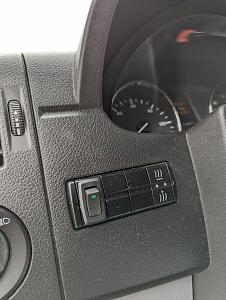
Sportsmobile installed this switch in 2018 and when I picked up the van I asked my salesman what it was for and he said it wasn't for anything, just a dummy switch of some sort. That didn't make much sense at the time but I took him at his word. It turns out it's a cutoff switch for the running boards. Because it was supposedly a dummy switch, I never messed with it, until the other day when I must have accidentally hit it and flipped it the other way. That turned off the running boards. Since the driver's door was open at the time, the left running board was stuck out while the one on the right was stuck in. Flipping the switch to the position seen in the photo resulted in everything working fine again.
I'm both very relieved but also feeling sheepish about this whole thing now, but mostly the former. Once I discovered the "problem" I lost interest in tracing most of the other wires around the relay and controllers. But I did sit down and draw up a crude wiring diagram with what I do know. It's hand drawn but gets the information across I think. Here it is if you're interested.
AMP Research Powerstep running boards wiring diagram.pdf
Since this post is long enough, I'll put my comments on your recent posts in another reply below.
|
|
|
|
|
03-24-2024, 05:12 PM
|
#17
|
|
Member
Join Date: May 2017
Posts: 64
|
Greg, you're guess was right on the money per my other post regarding the cutoff switch I "discovered" on my van dashboard. Thanks for that suggestion and all the other info you provided. It really helped me get a bit more understanding of the system although I still find it more confusing than I'd like it to be!
|
|
|
|
|
03-24-2024, 05:20 PM
|
#18
|
|
Member
Join Date: May 2017
Posts: 64
|
Big_ern_101,
I'm kind of backing off of criticizing AMP too much at this point given what I've found out about Sportsmobile's very non-standard install of the running boards.
You are right that the instructions I referred to has having been given by Sportsmobile were in fact just for the right side running board. They actually gave me two sets of instructions. I originally assumed the other set was for the driver's side but it turns out the second one was the same as the first set, i.e., for the passenger side. I suppose somewhat else out there in Sportsmobile land was given two sets of passenger side instructions and none for the left.
Since I have found the source of my problem, I'm going to leave well enough alone for now but keep in the back of my mind your suggestion about redoing the whole thing without the relay and only one controller using the dual side kit instructions. But I'll only do that if something actually goes wrong. In the meantime I will stick to the "if it ain't broke don't fix it" axiom.
Thanks again for all your help in pointing me in the right direction as much as you could with the sparse information I provided.
|
|
|
|
|
03-24-2024, 05:56 PM
|
#19
|
|
Senior Member
Join Date: May 2007
Location: Beaverton, OR
Posts: 2,506
|
LarryB, glad it ended up being that simple. I would send your findings back to Peter as Field Vans as that is completely on them. They should have had the switch documented. I guess if you have them deployed while camping, you can turn the switch and they will deployed. Just have to remember to bring in when you leave.
__________________
-greg
__________________________________________________ ______________
"Goldilocks" 2020 Ford Transit High Roof Extended 3.5 EcoBoost AWD Homebuilt
|
|
|
|
|
03-24-2024, 06:44 PM
|
#20
|
|
Member
Join Date: May 2017
Posts: 64
|
I've got an email in to Peter asking him what the relay was for. That's a good starting point for a discussion about this issue. Most definitely on them though, or on the salesman anyway.
|
|
|
|
|
|
 Posting Rules
|
You may not post new threads
You may not post replies
You may not post attachments
You may not edit your posts
HTML code is Off
|
|
|
|
 » Recent Threads
 |
|
|
|
|
|
|
|
|
|
|
|
|
|
|
|
|
|
|
|
|
|
|
|
|
|
|
|
|
|
|
|
|
|


 Linear Mode