|
|
 03-23-2024, 11:48 AM
|
#1
|
|
Member
Join Date: May 2017
Posts: 64
|
 AMP Research Powerstep running board problem
Hi All,
I have a 2017 MB Sprinter that Sportsmobile West built out for us in early 2018. Included in the build were the AMP PowerStep running boards. They have worked flawlessly until recently. Now neither side running board works. The driver's side is stuck in the down position while the passenger side is up. I had the driver's door open for a while today and the running board had deployed normally when the door was opened. But it did not close when the door was closed, nor did the board on the passenger side open when I opened a door on that side, so it must have decided to quit working while that one door was open. I was not working on anything at the time that this happened, although I had been to the car wash with it earlier.
I called AMP research for some help and their tech suggested that I remove the 30 amp fuse (under the driver's seat), which I did. (The red fuse holder is marked "BOARD.") I checked the fuse and it is not blown. the AMP tech also suggested leaving the fuse out for 10-15 minutes and then putting it back in, thinking that might reset the controller and get it working again. That didn't help either. Whenever I plugged the fuse in, I heard a click or two from the general area of of the controller wiring for the running boards, so I know the system is getting power.
After that things got a bit odd, as the tech said there should be just one controller running both running boards, but my system has two. He had never heard of that before and reiterated there should only be one. Also, he knew nothing about the little cube shaped box that wiring from both controllers runs to. I sent him photos of the setup and he said he'd never seen that little cube part before. He suggested just replacing both controllers and the cube and seeing if that fixed things.
After that I emailed Peter Del Toro at Field Van (a.k.a. Sportsmobile West). He said the little cube was a relay and that replacing it might well fix the problem. He also said they installed two controllers because that's what came with the kit.
So I located a replacement relay, same brand and item number as the old one and replaced it. But that didn't change anything.
I was able to get the running board that was stuck down to go back up by unplugging the wiring harness from its motor and then applying a 12v power source. So I know the motor at least on that side is not the problem.
So before spending a couple of hundred bucks replacing two controllers, I thought I'd as here if anyone has any other suggestions.
Here are some photos of the setup on my van:
This photo shows the two controllers side by side under the driver's seat.
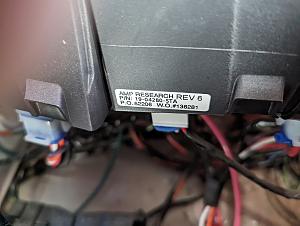
A closeup of one of the controllers showing the part number. (The other controller has the same label.)
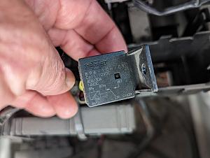
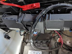
The relay that the battery power is connected to before going to the controllers. It was not mounted anywhere, just laying in the slot in the seat frame just below where you see it in the photo.
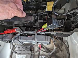
An overview of the setup showing the two controllers side by side, the red fuse holder above it and the relay to the right with wires attached to four spade terminals and another terminal with nothing attached to it.
Any suggestions would be greatly appreciated. Sorry for the long post!
|

|

|
|
03-23-2024, 02:51 PM
|
#2
|
|
Senior Member
Join Date: Mar 2023
Posts: 147
|
These AMP steps are really pretty simple at the end of the day, but I definitely have not seen one with two controllers.
Do you have a part number for the AMP kit that was installed, their instructions are online and they have pretty decent wiring info. No schematics but enough to figure it out. Since the kit was installed by SMB, maybe see if there is info in the documentation or they can provide the kit number.
The STA controller is capable of running all the steps, is it possible you have something like a power *rear* step by the rear bumber (would require a separate controller)?
How is the kit actuated? Do you have the OBD plug in or is it hardwired into the vehicle?
Can you follow the wiring from the two controllers and confirm that one controller runs the RH step and one controller runs the LH step? Are there any wires connected between the two controllers? Are there any abandoned or disconnected wires on the two controllers?
The STA controller is triggered by grounding a purple wire for one side and a purple with a black trace for the other side, if you can find the purple wires going in to the controller and ground them, the steps should actuate providing the motor and controller is good.
If I had to guess the relay is to convert a positive switched trigger (sprinter chassis side) to a ground trigger (powerstep side) Can you trace the wires from the relay to the vehicle and the controller and provide some more details?
When the steps worked properly, did they all come down together or did the RH side work with RH doors and LH side work with LH doors?
Do you have something like two independent boards on the passenger side? One for the slider and one for the passenger front door?
|
|
|
|
|
03-23-2024, 03:43 PM
|
#3
|
|
Member
Join Date: May 2017
Posts: 64
|
Thanks for the reply Big_ern_101,
The binder Sportsmobile gave me with all the manuals etc. for the van came with two identical sets of Powerstep installation guides. The part number is 75163-01A. The parts list in the guide shows only one controller. My guess is that Sportsmobile had separate kits in stock, one for the short left side and one for the long right side Powerstep. Since they were separate kits, rather than a single kit with two Powersteps, they ended up with two controllers so decided to install them separately instead of running both through the same controller.
I do not have any power rear step by the bumper or anything else. The wiring harnesses from the two controllers pass under the floor and then one to the LH step, the other to the single RH step. (Only one step, not two on the RH side.)
The power wire from the battery runs to the relay and then distributed (somehow) to the two controllers. I have not traced the other wires to the relay to see where they go yet. (Easy for wires to disappear somewhere without much indication of where they come out.)
I don't know how the kit is actuated. I'm not even sure how I'd track that down.
When the steps worked properly the RH and LH sides worked independently, i.e., only opened when the door on that side was open.
I downloaded a trouble shooting guide from AMP Research that looks like it might be helpful. It mentions that purple wire that you did and how to test it (basically what you said) so I will try that. (The van is in storage so I need to go get it, maybe tomorrow depending on weather--supposed to storm here tonight.) This sounds like the way to try and make sure the controllers are working. I was hoping for a way to test the controllers at home with my multi-tester as I pulled them out of the van and brought them home. I guess I'll need to bring the van home too.
Thanks for the suggestions. I hope I provided some useful info to you.
|
|
|
|
|
03-23-2024, 04:29 PM
|
#4
|
|
Senior Member
Join Date: Mar 2023
Posts: 147
|
So here is the good news. Chances are that both controller did not die at the same time, and you really only need one for full functionality.
The way the AMP controllers work you definitely COULD use two controllers by using one channel on each controller, but there is no need to.
If I was troubleshooting here is what I would do -
-Confirm you have power and ground at both controllers. Since they are both dead, thats the first place I would look.
-If you have power at both controllers, then ground both the purple wires at both controllers, or whatever purple wires you can find at the controllers. Tough to say without seeing how it is wired up.
If you have power and the purple wires are grounded, the steps should go down.
If the steps do NOT go down and you have power at the controllers, then you know the problem is either in the controllers or the motors. You tested at least one motor already, so chances are the motors are fine. Chances of blowing out both controllers is very slim.
If the steps DO go down when you ground the purple wires, the issue is between the controllers and the van chassis. Trace back to the relay, find the purple wires. If you ground the AMP controller trigger wires at the relay and the steps work, the issue is in the signals to the relay or a ground at the relay. If the steps do not work, then the issue is between the relay and the controllers.
Since the relay is custom, at this point you will need to rely on either Sportsmobile or your own electrical troubleshooting skills to fix it. As previously stated it is likely used to convert a positive trigger into the ground trigger the AMP steps need. Since you have two channels (LH and RH) that operate independently, you should have two relays.
This is an application where a Power Probe would be real handy, if you do not have one it would be nice to get one depending on how much you want to troubleshoot on your own.
Do your dome lights work and door open indicators on the dash? If these don't work, look for a blown fuse in the fusebox.
Stupid question but is it possible the dome light override has been turned on or turned off (so the dome lights are on or off constantly) and because of how SMB elected to trigger the steps, they are seeing either a constant on or off signal from the dome lights and not responding even though everything in the system is OK?
|
|
|
|
|
03-23-2024, 05:13 PM
|
#5
|
|
Senior Member
Join Date: May 2007
Location: Beaverton, OR
Posts: 2,506
|
I suspect that the relay is Dual Make SPST , pin 30 is common, probably from battery, pin 87 and pin 87b are both normally open output pins. One would go to each controller. The other two wires need to be a ground probably pin 85, and then a positive control on pin 86. There would be easier ways to split the power, so maybe it is a power control wire (for disconnecting during longer storage periods?)
__________________
-greg
__________________________________________________ ______________
"Goldilocks" 2020 Ford Transit High Roof Extended 3.5 EcoBoost AWD Homebuilt
|
|
|
|
|
03-23-2024, 06:15 PM
|
#6
|
|
Member
Join Date: May 2017
Posts: 64
|
BIr_er_101,
I fully agree both controllers most likely did not die at the same time. In fact the more I read about it from you and other sources, the more convinced I am it's something else that's causing the issue.
I'm going to try the troubleshooting you suggest--it's very close to what AMP Research suggests so I'll try both processes to cover all the bases.
You mentioned tracing wires to the relay and finding the purple ones. However there are no purple wires connected to the relay. If you zoom in on the last photo I posted you can kind of see the wires attached to the 5 spade pins on the relay. One just has a cover on it with no wire, to protect it from shorting I imagine. There is a single black wire (ground?) connected to the nearest pin in the photo. On the far side, barely visible is an orange wire. In between, one above the other are two pins, both with two heavier gauge red wires attached to them. I'm not sure without getting back in the van exactly where these wires all go but one red wire connects to the fuse holder and then to the battery positive post. And some of the wires connect to each controller.
I've got another email in to Peter at Field Van (Sportsmobile) asking about the relay. I don't have two relays as you suggest I should and I don't understand why I'd need one to convert a positive trigger into the ground trigger the AMP steps need, because the standard (one controller) installation package doesn't include a relay, rather it just connects directly to the battery and the controller (presumably) takes it from there.
I set my dome light to be off constantly, i.e., don't come on when the doors open, so that's not an issue. I do need to check if the door open indicator light comes on though--that's one thing AMP Research suggested checking too. Wouldn't that be nice if it was just a blown fuse? (Assuming a new one doesn't blow too.)
Thanks again for the help. I'll report back when I've been able to do more troubleshooting.
|
|
|
|
|
03-23-2024, 06:28 PM
|
#7
|
|
Member
Join Date: May 2017
Posts: 64
|
Greg,
I think you may be on the right track here, although the manufacturer website says it is a "SPDT" relay. You can see an electrical diagram for it in the 3rd of the 4 photos I posted. (Doesn't mean much to me but it likely does to you.) I think you're idea of what's connected to the pins is correct and I also agree that there would be easier ways to split the power. And I'm wondering why splitting a single power wire from the battery was done at all. Since the kit (according to Sportsmobile) came with two separate controllers I would have thought it would have contained two power wires and fuse holders as well, so they could have just attached both to the battery positive terminal and skipped the relay idea altogether. Must be something I'm missing here.
|
|
|
|
|
03-23-2024, 06:37 PM
|
#8
|
|
Senior Member
Join Date: May 2007
Location: Beaverton, OR
Posts: 2,506
|
Being that the relay is not using one of the pins, it looks like pin 87 or the normally open input. So does one of the pins have two red wires? I believe that is what you are saying. One of the other wires is ground (most likely the black) , the orange is probably positive. one of the two should be switched. If that is the case the relay doesn't have to be picked to pass power. In fact if energized it would disable. Possibly a disable switch? I would have thought that SMB documented it though.
__________________
-greg
__________________________________________________ ______________
"Goldilocks" 2020 Ford Transit High Roof Extended 3.5 EcoBoost AWD Homebuilt
|
|
|
|
|
03-23-2024, 06:57 PM
|
#9
|
|
Member
Join Date: May 2017
Posts: 64
|
Referring to the wiring diagram on the relay in the photo I posted, two of the pins, 87 and 87a, have two red wires attached to them. I'm thinking that one controller is attached to 87, the other to 87a? Why there are two red wires to 87 and 87a I don't know. I assumed one comes from the battery, but maybe that's what the orange wire does (even though the fuse holder has red wires on both sides.) I need to get back to the van to trace where all the wires go. I do know though that the orange wire is attached to pin 85, the black wire is attached to pin 86 and pin 30 is the one that is just covered with no wire coming to it.
|
|
|
|
|
03-23-2024, 08:21 PM
|
#10
|
|
Senior Member
Join Date: May 2007
Location: Beaverton, OR
Posts: 2,506
|
I would check and make sure one of the pairs isn't connected to pin 30. It would be the common input/output.

From the picture I would think 87a and 30 are connected. 87 & 87a would not do anything
__________________
-greg
__________________________________________________ ______________
"Goldilocks" 2020 Ford Transit High Roof Extended 3.5 EcoBoost AWD Homebuilt
|
|
|
|
|
|
 Posting Rules
|
You may not post new threads
You may not post replies
You may not post attachments
You may not edit your posts
HTML code is Off
|
|
|
|
 » Recent Threads
 |
|
|
|
|
|
|
|
|
|
|
|
|
|
|
|
|
|
|
|
|
|
|
|
|
|
|
|
|
|
|
|
|
|


 Linear Mode