Journey with Confidence RV GPS App RV Trip Planner RV LIFE Campground Reviews RV Maintenance Take a Speed Test Free 7 Day Trial ×


Reply
 
Thread Tools Display Modes
 
Old 06-02-2020, 07:31 PM   #21
Member
 
Join Date: Nov 2018
Location: Vermont
Posts: 38
Thanks for the help with photo posting. Seems to have rotated 90 degrees clockwise though. I believe one can see where the fuse block is cracked and broken. Where all the plastic is missing is where the blown fuse for the Aux condenser belongs.
Attached Thumbnails
IMG_2418.jpg  

Beejmac is offline   Reply With Quote
Old 06-02-2020, 07:46 PM   #22
Senior Member
 
arctictraveller's Avatar
 
Join Date: Mar 2013
Posts: 4,244
Finding that exact fuse holder may be difficult. The hardest part of installing a different shape holder may be that the wires are too short to make all the connections. Its hard to tell from the photo, but you may be able to salvage that one. First I'd clip the wire to the frozen fan and then try inserting a fuse and seeing if it makes contact with the metal blades. If so, you could probably use a zip tie to pull the holder together and be done with it. Another possibility would be to just get a single fuse holder, attach the white wire from the fuse block to one side of the new holder and the other side of the new holder to the large blue wire.
__________________
Arctic Traveller
KC6TNI
2001 GTRV
Advanced 4wd
Agile Ride improvement package
arctictraveller is offline   Reply With Quote
Old 06-03-2020, 04:24 AM   #23
Member
 
Join Date: Nov 2018
Location: Vermont
Posts: 38
Nice idea. When you say “frozen fan” do you literally mean will not rotate by manually spinning? I have been installing LED strip lighting and haven’t gotten there yet. The fan on the drivers side would trip the Aux condenser fuse?
Beejmac is offline   Reply With Quote
Old 06-03-2020, 05:23 AM   #24
Senior Member
 
BrianW's Avatar
 
Join Date: Apr 2012
Location: Philadelphia, PA
Posts: 4,208
Yes the fans will often seize up due to rust and other gunk from exposure. They then trip the breaker or blow a fuse on the Starcool block. It’s a common issue and the fans are easily replaced. Search the forum and you’ll find info and part numbers. I had to replace both of mine (under van and in front grille).
BrianW is offline   Reply With Quote
Old 06-03-2020, 05:58 AM   #25
Member
 
Join Date: Nov 2018
Location: Vermont
Posts: 38
Yup frozen solid.
Beejmac is offline   Reply With Quote
Old 06-03-2020, 12:37 PM   #26
Senior Member
 
Youngster's Avatar
 
Join Date: Jun 2016
Location: North of SanDiego
Posts: 233
This might help for sourcing the fan:

https://www.sportsmobileforum.com/fo...tml#post205786

https://www.summitracing.com/parts/MRG-1984MRG
__________________
2003 E-350, 5.4 V8, 2x4, LSD 4.10, WeldTec 6" lift, SMB, Penthouse
2016 Beta 500 RS
2014 KTM 350 EXC-F
Youngster is offline   Reply With Quote
Old 06-04-2020, 08:22 AM   #27
Senior Member
 
Scalf77's Avatar
 
Join Date: May 2007
Location: Beaverton, OR
Posts: 2,506
Quote:
Originally Posted by Beejmac View Post
I guess I don,t know how to test a relay, is it a visual inspection?
Are the relays so cheap I should just replace?
The Starcool relays are are riveted to the Starcool panel, not a huge deal, and you would have to be careful in making sure the wires got back in same place.

The Common SPDT Relay.


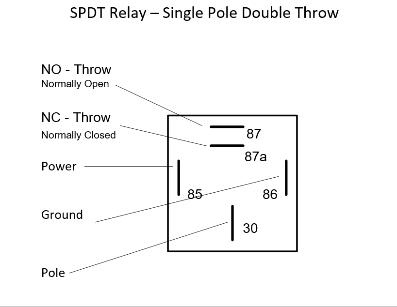
To test you can use a ohm meter to check the continuity between first The NC (87a) throw and Pole(30) connection, There is no power needed for that connection to be present. The NO(87) throw to Pole(30) connection should be open. You can apply power to the coil, generally tab (85) will be power and (86) will be ground, although the coil won't care. The polarity really becomes important if the relay has diode protection.

When power and ground are provided you can usually here a click as the trow moves. Now with a ohm meter check NO(87) to Pole(30), it should now show continuity. The NC(87a) connection to Pole(30) will now show open.

This is all done on the bench with the relay out of the circuit.With careful analysis of the circuit you can also validate if the relay is working in circuit. Unfortunately it can be difficult to reach some of the output pins.

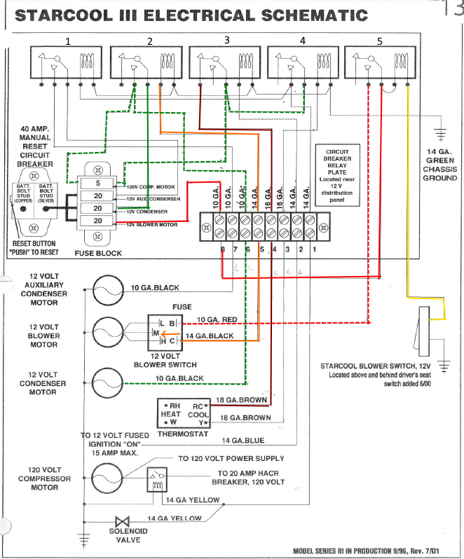
Here are the effects of the first switch, this is tied via a SPST switch from ground to ping 86 of relay (5). On older systems relay 5 and the switch may not be present as it was added in June of 2000. This allows power from the 20 amp fuse (12 blower Motor) via terminal block (pos 8) to the relay(5) Pole (30) connection and (85) to provide power. The switch normally positioned left side of drivers head will supply ground to the coil (86) and power will go trough the relay via NO (87) throw, and proceed to the input of the blower switch. It doesn't matter if the power switch is on or off it has no power


The next driving item will be the starcool blower switch. It provides a 12 volt output when it is in low,medium, or high. This will go through the terminal block (pos 5) to relay 2 power in (85). Now we have power coming from 20 amp fuse (12 volt condenser) to pin (30) of relay 2, now with power supplied to the relay pin (87) now has power. There are two paths (wires) for this output. Ones goes back to the fuse block 5 amp fuse (120 volt comp motor), the other goes yo the 12 volt condenser motor. The 5 amp fuse output goes to the pole (30) connection of both relay 3 and 4. In the case of relay 3, we have the NC (87A) connection wired via the terminal block (pos -4) and to the thermostat.


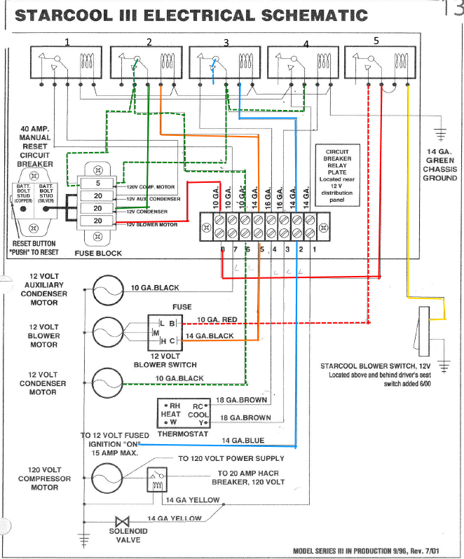
From this point we have two choices, running on shore power or assisting the 12 volt system while driving. If the thermostat temperature criteria is met the connection will continue to the terminal block(pos-3) to the power(85) pin of relay 4. As we already have 12 volts on the Pole (30) connection the 12 volts now goes out the NO -throw (87). This will split and supply power to via the terminal strip (position 1) to a relay for the 120 volt input, obviously the 120 volt breakers must be on. It also provides power for a 12 solenoid valve that redirects the flow of Freon in the system. The other connect goes to Relay 1 power pin (85).

The Pole (30) connection of relay 1 receives power from 20 amp fuse (12 volt aux condenser). Power will no flow through the relay and go out NO (86) connection via terminal strip (position 7) to the 12 volt Auxiliary Condenser Motor. At this time the air condition system should be working correctly. The thermostat will open and close as the temp criteria is met, the blowers will all be on.


The other mode is where the starcool is assisting the existing 12 volt air conditioning while the van is running. A 12 volt ignition on voltage is feed via the terminal block (position 2) to relay 3 Power (85). This will now remove power from the NC (87a) throw and provide it to the NO (87) connection which goes no where. In this case when we are running we remove power from of the specif components only needed when running 120 Volt shore power. One of those items is the 12 volt solenoid valve. So the freon system will revert back to assist mode.


A couple of key points, if not using shore power, make sure thermostat is not set to cool, and/or make sure the 120 starcool breaker is off. Make sure all the connections to the terminal strip are tight. If you turn off the van and the switches are still on you will hear various fans and such, but the air-conditioning is not working.

I know this response was late but may help others in the future.

-greg
__________________
-greg
__________________________________________________ ______________
"Goldilocks" 2020 Ford Transit High Roof Extended 3.5 EcoBoost AWD Homebuilt
Scalf77 is offline   Reply With Quote
Old 06-04-2020, 11:24 AM   #28
Senior Member
 
arctictraveller's Avatar
 
Join Date: Mar 2013
Posts: 4,244
Quote:
Originally Posted by Scalf77 View Post
The Starcool relays are are riveted to the Starcool panel,
Great detailed explanation of how the controls work. I didn't have any issues with the relays on my 2002 panel, but I have to say, I have never seen relays riveted into place. Every one I have ever worked on has simply plugged into a matching socket.
__________________
Arctic Traveller
KC6TNI
2001 GTRV
Advanced 4wd
Agile Ride improvement package
arctictraveller is offline   Reply With Quote
Old 06-04-2020, 11:26 AM   #29
Member
 
Join Date: Nov 2018
Location: Vermont
Posts: 38
Wow, what a resource.
BJM
Beejmac is offline   Reply With Quote
Old 06-04-2020, 05:56 PM   #30
Senior Member
 
Scalf77's Avatar
 
Join Date: May 2007
Location: Beaverton, OR
Posts: 2,506
Quote:
Originally Posted by arctictraveller View Post
I have never seen relays riveted into place. Every one I have ever worked on has simply plugged into a matching socket.
My van is 2004, I expect that they might have changed their panel, I have never seen sportsmobile use a socket for a relay, at least on mine.


-greg
__________________
-greg
__________________________________________________ ______________
"Goldilocks" 2020 Ford Transit High Roof Extended 3.5 EcoBoost AWD Homebuilt
Scalf77 is offline   Reply With Quote
Reply


Posting Rules
You may not post new threads
You may not post replies
You may not post attachments
You may not edit your posts

BB code is On
Smilies are On
[IMG] code is On
HTML code is Off
Trackbacks are Off
Pingbacks are Off
Refbacks are Off

» Featured Campgrounds

Reviews provided by

Powered by vBadvanced CMPS v3.2.3
Disclaimer:

This website is not affiliated with or endorsed by Sportsmobile SIP or any of its affiliates. This is an independent, unofficial site.


All times are GMT -6. The time now is 12:28 PM.


Powered by vBulletin® Version 3.8.8 Beta 4
Copyright ©2000 - 2024, vBulletin Solutions, Inc.