|
|
 07-03-2021, 10:45 AM
|
#31
|
|
Senior Member
Join Date: May 2007
Location: Beaverton, OR
Posts: 2,506
|
Quote:
Originally Posted by BCam

I know I raised the issue initially, but, from a practical standpoint, is the 25V limit that big a deal, particularly for most Sportsmobiles and vans?
The wire runs are short so I don't see a real need to minimize amp flow, which would be the main benefit of wiring panels in series as opposed to parallel. The DCC50S maxes out at 600W input, which shouldn't be an issue for most Sportsmobiles and vans
|
Bob, you would be correct. From a technical standpoint there is no reason that you could not design a working system with the 25V PV limit.
My preference would be something higher; at least to support 2x 36 cell panels in series or 1 x 72 cell panel. This would give you the most options choosing panels and lay out based on your needs.
One could even parallel two 72 cell panel together if they had room or needed that much power. Or more importantly the could modify their 2x36 cell bookcase portable panel to be in series and parallel with the existing 72 cell unit.
I have seen one hybrid panel that is actually two 36 cell panels, that you can configure in parallel or in series.
So the 25V limit is worth pointing out, but is workable
Quote:
Originally Posted by posplayr
I'm coming to the conclusion that an integrated solution where we can at the least do maintenance charging of the start battery when LiFePO4 bank has sufficient SOC is not only very possible but highly desirable. Further, a parallel connection of LA and LiFePO4 house batteries should be included in the mix. So conceptually this is coordinated management of mixed LA/LiFePO4 house with a LA start batteries.
Sounds perhaps complicated or dangerous or both? Maybe not.
|
From the standpoint of mixing the two technologies. I fully understand the concept, but it is not one that I want to push. My feeling is that this requires a little more knowledge, and battery management practice then the average person on this forum can or is willing to perform. The possibility for problems is there, it could certainly be manageable, but the potential for issues is higher. Not a big fan of the watch a YouTube video and become an expert either, especially when they tell you to go to their pay site to get more info. Although Clark is very upfront about it, it in a good way.
I was never big on the bidirectional (auto) even on common battery technologies, so it would follow that I would not be big on it for mismatched technologies. It is not apparent via the documentation how the DCC50S does the trickle charge, is it a combined float or separate trike charge circuit using left over PV power. They easily can easily isolate their DC-to-DC input because it is triggered via the run circuit, versus a monitoring the output voltage of the alternator. At the moment, this does not appear to be a must have feature that DC-to-DC charger manufacturers are pushing towards. But there are certainly other ways you can manage it.
I have isolated the input of another DC-to-DC charger with a relay, this allowed me a controlled path back to the start battery. I was able to charge both battery systems (LA Based) with either the shore charger or solar from the combined DC to DC charger. I have also used the same concept with a shore charger that had multiple battery outputs. The charger would charge the primary battery and then move to a secondary battery system. The primary could be set to Lithium and the secondary was limited to LA. One could install a separate small solar controller to perform charging duties for the start batteries. These are just a couple of possibilities, and one could get as simple or complicated as they want.
-greg
|

|

|
|
07-03-2021, 02:35 PM
|
#32
|
|
Senior Member
Join Date: May 2018
Location: Arizona
Posts: 675
|
Quote:
Originally Posted by Scalf77
I have isolated the input of another DC-to-DC charger with a relay, this allowed me a controlled path back to the start battery. I was able to charge both battery systems (LA Based) with either the shore charger or solar from the combined DC to DC charger. I have also used the same concept with a shore charger that had multiple battery outputs. The charger would charge the primary battery and then move to a secondary battery system. The primary could be set to Lithium and the secondary was limited to LA. One could install a separate small solar controller to perform charging duties for the start batteries. These are just a couple of possibilities, and one could get as simple or complicated as they want.
-greg
|
So there are two different topics here, that I want to avoid muddling to much for everybody else's benefit. The first is connecting LiFePO4 and LA in a house battery bank, the other is connecting a house battery bank to a start battery for trickle charging. I'll defer the discussion of the former and just deal with the second along the lines you have described.
So yes I agree, bidirectional charging amounts to some variation of an anti-parallel (back to back) battery charger arrangement (one to charge the Start battery the other to charge house battery).
What has had me hung up is that it is seductive to try and use some type of FET control to unidirectionally connect (with blocking diodes) the house batteries to the start batteries when the DC to DC LiFePO4 charging is off. This would be relatively simple and cheap while not being overly wasteful and unlikely to overcharge the start battery when using the limited voltage range of the LifePO house batteries. One issue with doing this is that there are too many other options while not necessarily elegant, that are just as cheap as any one-off DIY PCB design.
The next issue is this DIY FET approach would be that I would lose the isolation achieved with the DC-DC (at least the 40A Renogy that I have). So looking for an isolated solution, I could just get another Renogy 20A DC-DC for the other direction  but this has the downside of the fact that the DC -DC boost charger will drain your house battery trying to fully charge the start battery! Even with a 20A charger throttled back to 10A, this is a bit too much and would require some type of monitoring to shut down. I'm just looking for moderate to trickle charging.
The cheapest isolated solution that does not overtax the house battery is a 120VAC-12DC trickle charger. As an example (see the attached figure) I found an HF 4Amp charger (with an LCD display) that is easily controlled with an SSR. I used an automotive relay and switch to coordinate the activation of the antiparallel chargers.
The trickle charger can run off of shore power or using the onboard inverter. for a 4 A charging current the total house battery draw should not exceed 5A which is probably lower than the other solutions I was looking to DIY. I specifically chose a low amperage charger and so although this is not particularly efficient, it is probably not going to be too wasteful and it has the benefit of maintaining isolation between the house and start batteries.
For completeness, I also drew in the 10A Lead-acid Guest charger I already have and was planning to wire in on a timer for the house battery charging. It is a three-phase charger and seems to do well avoiding overcharging. With an onboard timer, I can use timer control for both 10A (house) and 4A (start) when running on shore power to provide more control overcharging.
So while running a trickle charger off of a 12V inverter is less than elegant, there is plenty of flexibility in this configuration and it is cheap and easy to configure between show power and off-grid and it maintains the isolation between the house and van systems. My main concern is wanting to charge the start battery is that I will want to run the in-dash stereo and have connections to a cell phone using car Play. I had considered rewiring the in-dash radio to run off the house but decided against that. This type of approach solves that problem while maintaining good isolation.
This is an effective bidirectional charging approach that avoids any "automatic" voltage sensing relays, maintains house to van/chassis isolation, and is available off the shelf in various forms. This is also essentially battery chemistry agnostic. In fact, there is nothing here incompatible with managing a Hybrid LiFePO4/LA house battery bank. But, I said I would defer that discussion till later so I'll leave I there .
|
|
|
|
|
07-03-2021, 03:49 PM
|
#33
|
|
Senior Member
Join Date: May 2007
Location: Beaverton, OR
Posts: 2,506
|
I agree that the Hybrid LiFePO4/LA house battery bank deserves it own thread and should not be buried in this thread.
We are some what aligned with ideas on charging the start via a Lithium house system. My current build is going to have a second alternator that is just for charging my lithium bank. At this time I have not decided on moving the stereo system to the house battery, I don't really use it a lot while camped. I did want to put a system in place to make the charging of my starting AGM's ( I currently have a Transit).
I am using a Victron Energy BPC121531104 Blue Smart Waterproof Battery Charger 12/15 with Bluetooth for a plug-in charger, this can be used when on shore power or not via the inverter. The second path for charging the start batteries is a Victron Energy SCC075015060 Smart Solar MPPT 75/15 Charge Controller. This is a small solar controller to handle the incoming 100-watt panel, that can be switched over from the main house solar system.
My Lithionics House battery is charged via the Xantrex Freedom XC Pro 3000 inverter/charger, second alternator with Wakespeed regulator, or via solar with my Tristar MPPT 60 amp controller by Morningstar.
-greg
|
|
|
|
|
03-10-2022, 03:42 PM
|
#34
|
|
Member
Join Date: Sep 2013
Location: Kentucky
Posts: 82
|
Switching to Lithium in 2014 Sportsmobile
This thread has great information from Greg with the wiring diagrams, etc. It is very helpful.
We just returned from a 3 1/2 week trip down south. We found out on the trip that our house battery was going bad.
So we have made the decision to switch to lithium. We are looking at Battle Born lithium batteries (GC2).
I have room in our 2014 Sportsmobile to install 3 of the Battle Born GC2 lithium batteries (100Ah each). I plan to install them inside the van and remove the dangling exterior AGM house battery in the back. After talking to a Battle Born tech person, I have almost all of my questions answered for the conversion to Lithium.
Battle Born recommends purchasing a new battery isolator they recommend and sell on their website. It is the LiFePO4 Battery Isolation Manager (LI-BIM 225).
We currently have a Blue Sea System (ML-ARC 7620) charging relay in the van that was installed in the original Sportsmobile build.
My assumption is that I can pull out the Blue Sea System charging relay and replace it with the LiFePO4 Battery Isolation Manager. Is this a correct assumption?
I understand the house battery connection and the engine battery connection, as well as the ground connection for the new LiFePO4 Battery Isolation Manager.
On the Blue Sea System charging relay there is a wiring bus that comes out of the bottom. There are only two wires connected on our build, a red wire and a black wire. The other wires are not connected. The black is connected to the grounding block in our van. The red wire is connected to something, I assume it is the ignition switch, or is it connected to something else?
That is my question I have for Greg or other members on the Forum.
Also, do I need to connect the sig nut to something? Looks like it goes to a switch to connect both batteries manually for charging.
I appreciate any guidance!
Thank you for your help,
Patrick & Angie Jennings
__________________
Patrick and Angie
2014 Ford SMB EB 50 4x4
2012 Toyota 4Runner 4x4
2017 Subaru Crosstrek
|
|
|
|
|
03-10-2022, 04:04 PM
|
#35
|
|
Senior Member
Join Date: May 2007
Location: Beaverton, OR
Posts: 2,506
|
So, you do need to verify that the ACR has a ground connection, that is the black wire and that the red wire is connected to the "ignition" or run circuit. This needs to be hot "12 Volts" when the engine is running. To be honest it really should not be connected that way if you want it to work correctly, but there have been many sportsmobile that were wired wrong. wired this way defeats the voltage monitoring and disconnect feature while the van is running
It is also possible that sportsmobile wired the red wire to switch, for jump start option.
The BIM will need the ground and a ignition circuit, the sig signal is for jump start option, and can be momentary to ground or 12 volts.
-greg
|
|
|
|
|
03-10-2022, 05:27 PM
|
#36
|
|
Member
Join Date: Sep 2013
Location: Kentucky
Posts: 82
|
Quote:
Originally Posted by Scalf77
So, you do need to verify that the ACR has a ground connection, that is the black wire and that the red wire is connected to the "ignition" or run circuit. This needs to be hot "12 Volts" when the engine is running. To be honest it really should not be connected that way if you want it to work correctly, but there have been many sportsmobile that were wired wrong. wired this way defeats the voltage monitoring and disconnect feature while the van is running
It is also possible that sportsmobile wired the red wire to switch, for jump start option.
The BIM will need the ground and a ignition circuit, the sig signal is for jump start option, and can be momentary to ground or 12 volts.
-greg
|
I have never had any problems with the voltage metering.
There is a ground connection. I'll need to check if there is a 12 volt current running in the "red" wire.
I think our build is wired correctly.
When out camping in the van when I get up in the morning and start the Sportsmobile the charging relay will kick in, "thunk", and the voltage will go from 12.xx up to 13.xx volts and start charging the house battery without any issue. We see the charging on the Magnum MC Remote installed in our build.
I am not sure if the red wire is connected to the jump start option or not. That is what I am trying to figure out from everyone before I crosswire something.
I am a bit confused about the sig signal, should I just connect it to the ground?
Thanks for your quick feedback and help Greg.
Patrick And Angie Jennings
__________________
Patrick and Angie
2014 Ford SMB EB 50 4x4
2012 Toyota 4Runner 4x4
2017 Subaru Crosstrek
|
|
|
|
|
03-10-2022, 06:10 PM
|
#37
|
|
Senior Member
Join Date: May 2007
Location: Beaverton, OR
Posts: 2,506
|
The Sig signal needs to be switched, a momentary switch is preferred. It actually can be tied to either ground or 12 volts thru the switch to force the jump start option.
Sportsmobile may have wired the red connection to the "Start Circuit" 12 volts when key is in start. This would be a carry over of the surepower unit. If that is the case it will not work for the BIM.
If it was wired wrong and hooked to the run circuit, then you could use that wire. but you need to check that it is 12 volts when running only.
So in this case you would hope that they wired it wrong, which would not have prevented the ACR from connecting correctly, but it would keep it from disconnecting if the voltage dropped below 12.8 while running
-greg
|
|
|
|
|
03-11-2022, 08:29 AM
|
#38
|
|
Senior Member
Join Date: May 2007
Location: Beaverton, OR
Posts: 2,506
|
Adding a Precision Circuits LI BIM 225 diagram. This is pretty much like a ACR but for lithium batteries. The BIM will allow charging of Lithium straight with alternator, the draw back is that it will limit charging to about 80% SOC. It will also charge the chassis battery when plugged into shore power or solar.
I would make sure that you are comfortable with the charging settings for your start batteries
It does provide a jump start solution, which is a bonus to some. The sig signal if left floating won't do anything. If you switch it to ground or 12 volts it will force the batteries to connect for jumpstarting. It really depends on which method is easier for the installer. It is recommended to be a momentary switch.

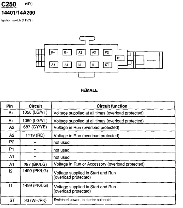
Also the location sportsmobile usually taps into the start or run circuit is this connector on the steering column. This is from a 2004 V10 , I am not sure how much it changes for year and engine type.
-greg
greg
|
|
|
|
|
06-22-2023, 07:09 PM
|
#39
|
|
Member
Join Date: Oct 2016
Location: North County San Diego
Posts: 55
|
The alternator went bad in my 2003 7.3L SMB RB50 with a house battery. I hastily ordered a Mean Green high output replacement (might have been drinking).
I also realized that my Sure Power isolator may be original.
My questions are: Should I keep the Mean Green or return and get a US made high amp? Or stick with a regular stock alternator? Do I need to increase the size of the alternator cable?
Clearly I need to replace the isolator. The Perfect Switch looks like an easy swap-- or do I go with a BlueSea ACR? It looks like I would need to wire the alternator to the distribution box and run the BlueSea ACR off of the battery? Does the 2 starting batteries make thing interesting?
Lastly-- is it possible to move the distribution box to get to the SurePower or just go thought the headlight?
Thanks in advance.
|
|
|
|
|
06-22-2023, 08:09 PM
|
#40
|
|
Senior Member
Join Date: May 2007
Location: Beaverton, OR
Posts: 2,506
|
Your Diode based isolator is most likely targeted for the original alternator, so chances are that your new one (didn't really see any specs. although didn't look hard) is two large for it.
The perfect switch would be more of a drop in replacement, but you most likely need to upsize the wires depending on alt output.
If you are to switch over to a ACR you first need to put Alt back to stock (uninstall the isolator) . Then choose appropriate sized wire based alt output and length of wire.
I would suspect a higher output alternator would be the way to go, but it will have some down stream upgrades that need to happen.
-greg
|
|
|
|
|
|
 Posting Rules
|
You may not post new threads
You may not post replies
You may not post attachments
You may not edit your posts
HTML code is Off
|
|
|
|
 » Recent Threads
 |
|
|
|
|
|
|
|
|
|
|
|
|
|
|
|
|
|
|
|
|
|
|
|
|
|
|
|
|
|
|
|
|
|


 Linear Mode